Nissan Leaf. Manual - part 313
BRC-42
< SYSTEM DESCRIPTION >
[WITH VDC]
SYSTEM
• The electrically-driven intelligent brake unit transmits a brake warning lamp request signal to the ABS actua-
tor and electric unit (control unit) via CAN communication when detecting a malfunction in the electrically-
driven intelligent brake unit.
• The ABS actuator and electric unit (control unit) receiving a brake warning lamp request signal, and trans-
mits a brake system warning lamp signal to the combination meter via CAN communication.
• The combination meter turns ON the brake system warning lamp when receiving a brake system warning
lamp signal.
• For the relationship between warning lamp and DTC, refer to
.
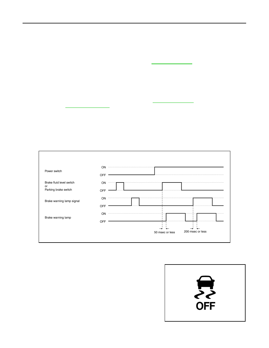
LIGHTING CONDITION
When any of the condition listed below is satisfied while the power switch ON:
• Brake fluid level switch ON.
• Parking switch ON.
• A malfunction is detected in the EBD function of the ABS actuator and electric unit (control unit).
• A malfunction is detected in the electrically-driven intelligent brake unit.
• For the relationship between warning lamp and DTC, refer to
(electrically-driven intelli-
gent brake unit) or
[ABS actuator and electric unit (control unit)].
SHUTOFF CONDITION
• When the condition listed below is satisfied while the power switch ON:
- Brake fluid level switch is OFF.
- Parking brake switch is OFF.
- Erase DTC
• Power switch OFF
TIMING CHART
WARNING/INDICATOR/CHIME LIST : VDC OFF Indicator Lamp
INFOID:0000000010120041
DESIGN/PURPOSE
The VDC OFF indicator lamp warns the driver that VDC function and
TCS function are OFF.
BULB CHECK
The VDC OFF indicator lamp turns ON and stays ON for several seconds after turning ON the power switch.
JSFIA1853GB
JPNIA1867ZZ