Nissan Leaf. Manual - part 240


  Index      Nissan     Nissan Leaf (2011-2014 year) - Service and Repair Manual


Search            


Content   ..  238  239  240  241   ..


Nissan Leaf. Manual - part 240


C1A90 CONTROL MODULE

BR-281

< DTC/CIRCUIT DIAGNOSIS >

C

D

E

G

H

I

J

K

L

M

A

B

BR

N

O

P

C1A90 CONTROL MODULE

DTC Logic

INFOID:0000000010123057

DTC DETECTION LOGIC

DTC REPRODUCTION PROCEDURE

1.

PRECONDITIONING

If “DTC CONFIRMATION PROCEDURE” has been previously conducted, always turn power switch OFF and

wait at least 10 seconds before conducting the next test.

>> GO TO 2.

2.

CHECK DTC DETECTION

With CONSULT

1. Turn the power switch OFF to ON without depressing the brake pedal.

CAUTION:

Never set the vehicle to READY.

2. Start CONSULT and perform “BRAKE” self-diagnosis.
Is DTC “C1A90” detected?

YES

>> Proceed to 

BR-281, "Diagnosis Procedure"

.

NO

>> INSPECTION END

Diagnosis Procedure

INFOID:0000000010123058

1.

PERFORM SELF-DIAGNOSIS (1)

With CONSULT

1. Turn the power switch OFF to ON without depressing the brake pedal.

CAUTION:

Never set the vehicle to READY.

2. Start CONSULT and perform “BRAKE” self-diagnosis.
“PAST” or “CRNT” shown in self-diagnosis results (“C1A90”)?

YES (“PAST”)>>GO TO 2.

YES (“CRNT”)>>GO TO 6.

NO

>> INSPECTION END

2.

INTERVIEW FROM THE CUSTOMER (1)

Check to see if there is a removal history of 12V battery or 12V battery terminals.
Is there a removal history of 12V battery or 12V battery terminals?

YES

>> GO TO 3.

NO

>> GO TO 6.

3.

INTERVIEW FROM THE CUSTOMER (2)

Check to see if there is a lighting history of the brake system warning lamp (yellow).
Is there a lighting history of the brake system warning lamp (yellow)?

YES

>> GO TO 6.

NO

>> GO TO 4.

4.

INTERVIEW FROM THE CUSTOMER (3)

Check to see if the customer has an experience of feeling unusual braking force (brake pedal operation).
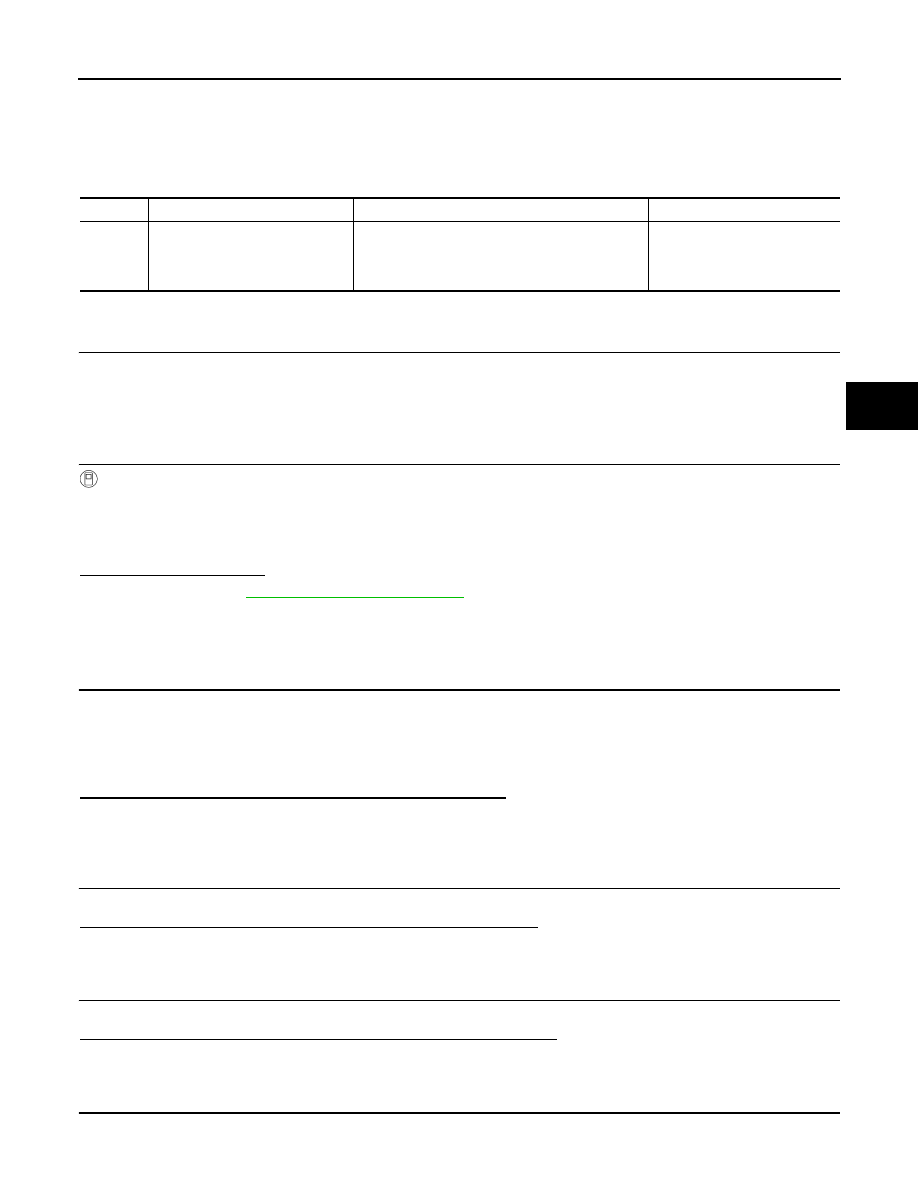
DTC

Display item

Malfunction detection condition

Possible causes

C1A90

POWER SUPPLY MODE

Power supply to the electrically-driven intelligent 
brake unit is switched from 12V battery to the brake 
power supply backup unit and the warning buzzer 
is activated.

• Harness or connector
• Electrically-driven intelligent 

brake unit

BR-282

< DTC/CIRCUIT DIAGNOSIS >

C1A90 CONTROL MODULE

Does the customer have an experience of feeling unusual braking force?

YES

>> GO TO 6.

NO

>> GO TO 5.

5.

PERFORM SELF-DIAGNOSIS (2)

With CONSULT

1. Turn the power switch OFF to ON without depressing the brake pedal.

CAUTION:

Never set the vehicle to READY.

2. Repeat step 1 two or more times.

CAUTION:

Be sure to wait for 5 seconds or more after turning the power switch OFF.

3. Turn the power switch OFF to exit CONSULT, and disconnect CONSULT from data link connector.

4. Close all doors (including back door), check that the room lamp is OFF, get out of the vehicle, and wait for

3 minutes or more with all doors closed.

CAUTION:

Never operate the vehicle while waiting.

5. Turn the power switch ON without depressing the brake pedal.

CAUTION:

Never set the vehicle to READY.

6. Start CONSULT and erase self-diagnosis result of “BRAKE”.

7. Turn the power switch OFF to exit CONSULT, and disconnect CONSULT from data link connector.

8. Close all doors (including back door), check that the room lamp is OFF, get out of the vehicle, and wait for

3 minutes or more with all doors closed.

CAUTION:

Never operate the vehicle while waiting.

9. Turn the power switch ON without depressing the brake pedal.

CAUTION:

Never set the vehicle to READY.

10. Depress brake pedal by 100 mm (3.94 in) or more, and hold the position for 5 seconds or more.

11. Release brake pedal.

12. Start CONSULT and perform “BRAKE” self-diagnosis.
Is DTC “C1A90” detected?

YES

>> GO TO 6.

NO

>> INSPECTION END [DTC “C1A90” is detected when12V battery terminals are disconnected after

turning the power switch OFF with any door open (including back door) or without waiting 3 min-

utes after closing all doors (including back door).]

6.

CHECK 12V BATTERY

1. Turn the power switch OFF to exit CONSULT, and disconnect CONSULT from data link connector.

2. Close all doors (including back door), check that the room lamp is OFF, get out of the vehicle, and wait for

3 minutes or more with all doors closed.

CAUTION:

Never operate the vehicle while waiting.

3. Check the 12V battery terminal connections. Refer to 

BR-6, "Precaution for Removing 12V Battery"

 and

PG-83, "Work Flow"

.

4. Check the 12V battery. Refer to 

PG-83, "Work Flow"

.

Is the inspection result normal?

YES

>> GO TO 7.

NO

>> Repair or replace error-detected parts and GO TO 7.

7.

PERFORM SELF-DIAGNOSIS (3)

With CONSULT

1. Connect 12V battery cable to negative terminal.

2. Turn the power switch OFF to ON without depressing the brake pedal.

CAUTION:

Never set the vehicle to READY.

3. Repeat step 2 two or more times.

CAUTION:

Be sure to wait for 5 seconds or more after turning the power switch OFF.

C1A90 CONTROL MODULE

BR-283

< DTC/CIRCUIT DIAGNOSIS >

C

D

E

G

H

I

J

K

L

M

A

B

BR

N

O

P

4. Turn the power switch OFF to exit CONSULT, and disconnect CONSULT from data link connector.

5. Close all doors (including back door), check that the room lamp is OFF, get out of the vehicle, and wait for

3 minutes or more with all doors closed.

CAUTION:

Never operate the vehicle while waiting.

6. Turn the power switch ON without depressing the brake pedal.

CAUTION:

Never set the vehicle to READY.

7. Start CONSULT and erase self-diagnosis result of “BRAKE”.

8. Turn the power switch OFF to exit CONSULT, and disconnect CONSULT from data link connector.

9. Close all doors (including back door), check that the room lamp is OFF, get out of the vehicle, and wait for

3 minutes or more with all doors closed.

CAUTION:

Never operate the vehicle while waiting.

10. Turn the power switch ON without depressing the brake pedal.

CAUTION:

Never set the vehicle to READY.

11. Depress brake pedal by 100 mm (3.94 in) or more, and hold the position for 5 seconds or more.

12. Release brake pedal.

13. Start CONSULT and perform “BRAKE” self-diagnosis.
Is DTC “C1A90” detected?

YES

>> GO TO 8.

NO

>> INSPECTION END

8.

CHECK CONNECTOR TERMINALS

1. Turn the power switch OFF to exit CONSULT, and disconnect CONSULT from data link connector.

2. Close all doors (including back door), check that the room lamp is OFF, get out of the vehicle, and wait for

3 minutes or more with all doors closed.

CAUTION:

Never operate the vehicle while waiting.

3. Disconnect 12V battery cable from negative terminal. Refer to 

BR-6, "Precaution for Removing 12V Bat-

tery"

.

4. Disconnect the electrically-driven intelligent brake unit harness connector, then check for failures of pin

terminals and connections.

Is the inspection result normal?

YES

>> GO TO 9.

NO

>> Repair or replace error-detected parts and GO TO 9.

9.

PERFORM SELF-DIAGNOSIS (4)

With CONSULT

1. Connect the electrically-driven intelligent brake unit harness connector.

2. Connect 12V battery cable to negative terminal.

3. Turn the power switch OFF to ON without depressing the brake pedal.

CAUTION:

Never set the vehicle to READY.

4. Repeat step 3 two or more times.

CAUTION:

Be sure to wait for 5 seconds or more after turning the power switch OFF.

5. Turn the power switch OFF to exit CONSULT, and disconnect CONSULT from data link connector.

6. Close all doors (including back door), check that the room lamp is OFF, get out of the vehicle, and wait for

3 minutes or more with all doors closed.

CAUTION:

Never operate the vehicle while waiting.

7. Turn the power switch ON without depressing the brake pedal.

CAUTION:

Never set the vehicle to READY.

8. Start CONSULT and erase self-diagnosis result of “BRAKE”.

9. Turn the power switch OFF to exit CONSULT, and disconnect CONSULT from data link connector.

10. Close all doors (including back door), check that the room lamp is OFF, get out of the vehicle, and wait for

3 minutes or more with all doors closed.

BR-284

< DTC/CIRCUIT DIAGNOSIS >

C1A90 CONTROL MODULE

CAUTION:

Never operate the vehicle while waiting.

11. Turn the power switch ON without depressing the brake pedal.

CAUTION:

Never set the vehicle to READY.

12. Depress brake pedal by 100 mm (3.94 in) or more, and hold the position for 5 seconds or more.

13. Release brake pedal.

14. Start CONSULT and perform “BRAKE” self-diagnosis.
Is DTC “C1A90” detected?

YES

>> GO TO 10.

NO

>> INSPECTION END

10.

CHECK POWER SWITCH ON POWER SUPPLY 

1. Connect 12V battery cable to negative terminal.

2. Turn the power switch OFF to exit CONSULT, and disconnect CONSULT from data link connector.

3. Close all doors (including back door), check that the room lamp is OFF, get out of the vehicle, and wait for

3 minutes or more with all doors closed.

CAUTION:

Never operate the vehicle while waiting.

4. Disconnect 12V battery cable from negative terminal. Refer to 

BR-6, "Precaution for Removing 12V Bat-

tery"

.

5. Disconnect the electrically-driven intelligent brake unit harness connector.

6. Connect 12V battery cable to negative terminal.

7. Check the voltage between the electrically-driven intelligent brake unit harness connector and ground.

8. Turn the power switch ON without depressing the brake pedal.

CAUTION:

Never set the vehicle to READY.

9. Check the voltage between the electrically-driven intelligent brake unit harness connector and ground.

Is the inspection result normal?

YES

>> GO TO 13.

NO

>> GO TO 11.

11.

CHECK POWER SWITCH ON POWER SUPPLY CIRCUIT 

1. Turn the power switch OFF to exit CONSULT, and disconnect CONSULT from data link connector.

2. Close all doors (including back door), check that the room lamp is OFF, get out of the vehicle, and wait for

3 minutes or more with all doors closed.

CAUTION:

Never operate the vehicle while waiting.

3. Disconnect 12V battery cable from negative terminal. Refer to 

BR-6, "Precaution for Removing 12V Bat-

tery"

.

4. Check the 15A fuse (#62).

5. Disconnect IPDM E/R harness connector.

6. Check the continuity between electrically-driven intelligent brake unit and IPDM E/R.

7. Check the continuity between electrically-driven intelligent brake unit harness connector and ground.

Electrically-driven intelligent brake unit

Voltage

(Approx.)

Connector

Terminal

E34

26

Ground

0 V

Electrically-driven intelligent brake unit

Voltage

(Approx.)

Connector

Terminal

E34

26

Ground

10 

− 16 V

Electrically-driven intelligent brake unit

IPDM E/R

Continuity

Connector

Terminal

Connector

Terminal

E34

26

E15

62

Existed


Content   ..  238  239  240  241   ..