Nissan Leaf. Manual - part 1288


  Index      Nissan     Nissan Leaf (2011-2014 year) - Service and Repair Manual


Search            


Content   ..  1286  1287  1288  1289   ..


Nissan Leaf. Manual - part 1288


C1729 VEHICLE SPEED SIGNAL

WT-31

< DTC/CIRCUIT DIAGNOSIS >

C

D

F

G

H

I

J

K

L

M

A

B

WT

N

O

P

C1729 VEHICLE SPEED SIGNAL

DTC Logic

INFOID:0000000010120195

DTC DETECTION LOGIC

DTC CONFIRMATION PROCEDURE

1.

DTC CONFIRMATION PROCEDURE

 With CONSULT

1. Drive the vehicle.

2. Stop the vehicle.

3. Perform “Self Diagnostic Result“” in “AIR PRESSURE MONITOR” of “BCM”.
Is DTC “C1729” detected?

YES

>> Proceed to 

WT-31, "Diagnosis Procedure"

.

NO

>> Inspection End.

Diagnosis Procedure

INFOID:0000000010120196

1.

PERFORM ABS ACTUATOR AND ELECTRIC UNIT (CONTROL UNIT) SELF DIAGNOSTIC RESULT

 With CONSULT

Perform “Self Diagnostic Result””“ for “ABS”.
Are any DTCs detected?

YES

>> Refer to 

BRC-56, "DTC Index"

.

NO

>> GO TO 2.

2.

CHECK BCM INPUT/OUTPUT SIGNAL

Check the BCM input/output signal values. Refer to 

BCS-28, "Reference Value"

Is the inspection result normal?

YES

>> Check pin terminal and connection of each harness connector for malfunctioning conditions. 

NO

>> Replace the BCM. Refer to 

BCS-72, "Removal and Installation"
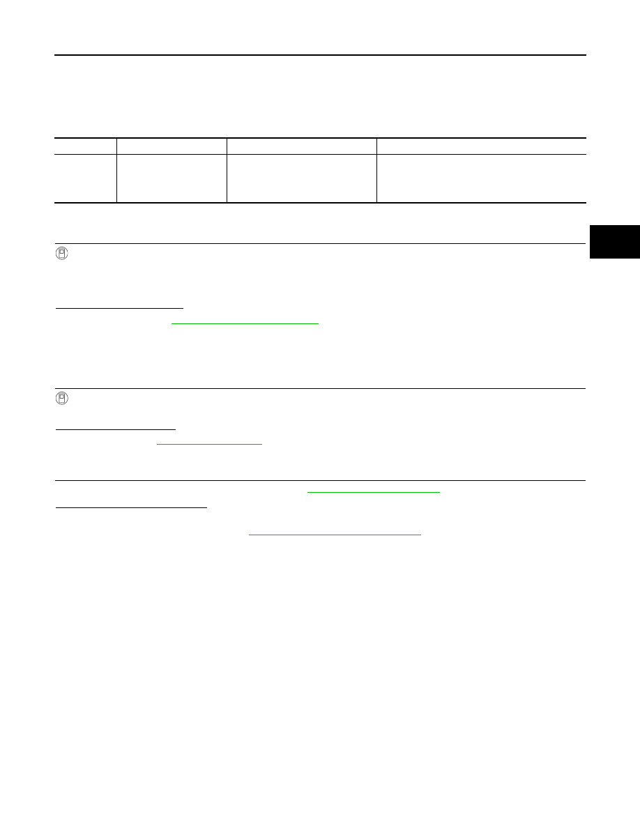
.

DTC

Display Item

Malfunction detected condition

Possible causes

C1729

VHCL SPEED SIG ERR

Vehicle speed signal not detected.

• CAN communication
• BCM
• ABS actuator and electric unit (control unit) mal-

function

WT-32

< DTC/CIRCUIT DIAGNOSIS >

POWER SUPPLY AND GROUND CIRCUIT

POWER SUPPLY AND GROUND CIRCUIT

Diagnosis Procedure

INFOID:0000000010120197

Regarding Wiring Diagram information, refer to 

WT-15, "Wiring Diagram"

.

1.

CHECK FUSE AND FUSIBLE LINK

Check that the following fuse and fusible link are not blown:

Is the fuse or fusible link blown?

YES

>> Replace the blown fuse or fusible link after repairing the affected circuit.

NO

>> GO TO 2.

2.

CHECK POWER SUPPLY CIRCUIT

1. Disconnect BCM connector M25.

2. Check voltage between BCM connector M25 and ground.

Is the inspection result normal?

YES

>> GO TO 3.

NO

>> Repair or replace harness or connectors.

3.

CHECK GROUND CIRCUIT

Check continuity between BCM connector M25 and ground.

Is the inspection result normal?

YES

>> Inspection End.

NO

>> Repair or replace harness or connectors.

Terminal No.

Signal name

Fuse and fusible link No.

57

Battery power supply

9 (10A)

70

H (40A)

BCM

Ground

Voltage

(Approx.)

Connector

Terminal

M25

57

Battery voltage

70

BCM

Ground

Continuity

Connector

Terminal

M25

67

Yes

TPMS

WT-33

< SYMPTOM DIAGNOSIS >

C

D

F

G

H

I

J

K

L

M

A

B

WT

N

O

P

SYMPTOM DIAGNOSIS

TPMS

Symptom Table 

INFOID:0000000010120198

LOW TIRE PRESSURE WARNING LAMP SYMPTOM CHART

WT-34

< SYMPTOM DIAGNOSIS >

TPMS

Diagnosis 

items

Symptom

(Power switch ON)

Low tire pressure warning lamp

Cause

Action

Low tire pres-
sure warning 
lamp

The low tire pres-
sure warning lamp 
illuminates for 1 
second, then turns 
OFF.

Wake-up operation for 
all tire pressure sensors 
at wheels is completed.

No system malfunctions.

The low tire pres-
sure warning lamp 
repeats blinking 
ON for 2 seconds 
and OFF for 0.2 
seconds.

Wake-up operation for 
all tire pressure sensors 
at wheels is not complet-
ed.

Perform the ID registration 
for all tire pressure sensors 
at wheels. Refer to 

WT-21, 

"Work Procedure"

.

The low tire pres-
sure warning lamp 
blinks once.

The front left tire pres-
sure sensor is not acti-
vated.

Perform the ID registration 
for the tire pressure sensor 
at front left wheel. Refer to 

WT-21, "Work Procedure"

.

The low tire pres-
sure warning lamp 
repeats blinking 
twice.

The front right tire pres-
sure sensor is not acti-
vated.

Perform the ID registration 
for the tire pressure sensor 
at front right wheel. Refer 
to  

WT-21, "Work Proce-

dure"

.

The low tire pres-
sure warning lamp 
repeats blinking 
for 3 times.

The rear right tire pres-
sure sensor is not acti-
vated.

Perform the ID registration 
for the tire pressure sensor 
at rear right wheel. Refer to  

WT-21, "Work Procedure"

.

The low tire pres-
sure warning lamp 
repeats blinking 
for 4 times.

The rear left tire pres-
sure sensor is not acti-
vated.

Perform the ID registration 
for the tire pressure sensor 
at rear left wheel. Refer to 

WT-21, "Work Procedure"

.

The low tire pres-
sure warning lamp 
turns ON and 
stays illuminated.

Low tire pressure.

Check the tire pressure for 
all wheels and adjust to the 
specified value. Refer to 

WT-51, "Tire Air Pressure"

SEIA0592E

SEIA0593E

JPEIC0090GB

SEIA0595E

SEIA0596E

SEIA0597E

SEIA0598E


Content   ..  1286  1287  1288  1289   ..