Nissan Leaf. Manual - part 121


  Index      Nissan     Nissan Leaf (2011-2014 year) - Service and Repair Manual


Search            


Content   ..  119  120  121  122   ..


Nissan Leaf. Manual - part 121


AV

MULTI AV SYSTEM

AV-475

< SYMPTOM DIAGNOSIS >

[NAVIGATION WITH BOSE]

C

D

E

F

G

H

I

J

K

L

M

B

A

O

P

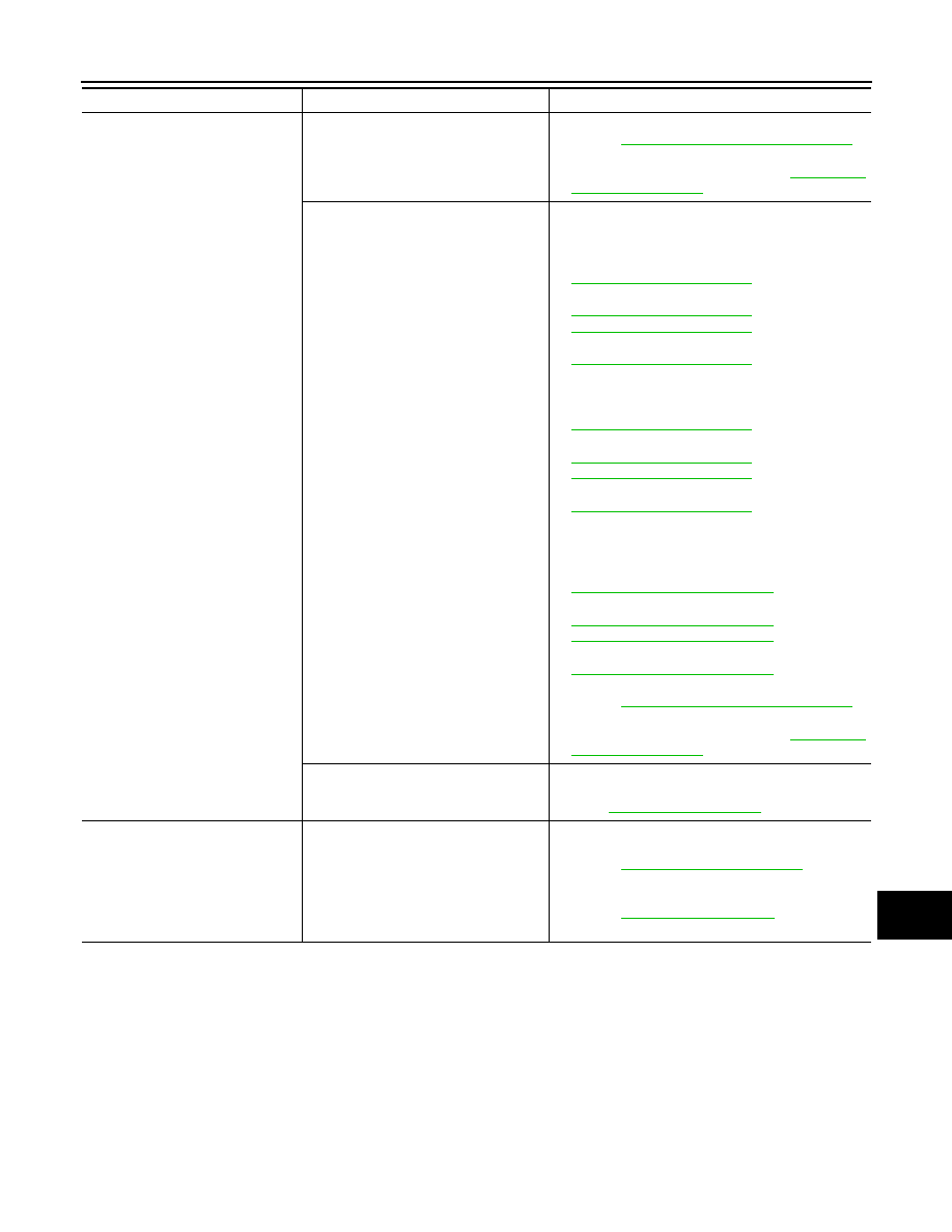
Noise is mixed with audio.

Noise comes out from all speakers.

• Malfunction in AV control unit.

Refer to 

AV-367, "On Board Diagnosis Function"

.

• Malfunction in Bose speaker amp.

Replace Bose speaker amp. Refer to 

AV-501, "Re-

moval and Installation"

.

Noise comes out only from a certain 
speaker (front door speaker LH, front 
door speaker RH, tweeter LH, tweeter 
RH, rear door speaker LH, rear door 
speaker RH, subwoofer).

• Poor connector connection of speaker.
• Sound signal circuit malfunction between AV con-

trol unit and Bose speaker amp.
Refer to:

-

AV-456, "Diagnosis Procedure"

 (front door speak-

er).

-

AV-459, "Diagnosis Procedure"

 (tweeter).

-

AV-462, "Diagnosis Procedure"

 (rear door speak-

er).

-

AV-465, "Diagnosis Procedure"

 (subwoofer).

• Sound signal circuit malfunction between Bose 

speaker amp. and speaker.
Refer to:

-

AV-456, "Diagnosis Procedure"

 (front door speak-

er).

-

AV-459, "Diagnosis Procedure"

 (tweeter).

-

AV-462, "Diagnosis Procedure"

 (rear door speak-

er).

-

AV-465, "Diagnosis Procedure"

 (subwoofer).

• Malfunction in speaker.
• Poor Installation of speaker (e.g. backlash and 

looseness).
Refer to:

-

AV-490, "Removal and Installation"

 (front door 

speaker).

-

AV-491, "Removal and Installation"

 (tweeter).

-

AV-492, "Removal and Installation"

 (rear door 

speaker).

-

AV-500, "Removal and Installation"

 (subwoofer).

• Malfunction in AV control unit.

Refer to 

AV-367, "On Board Diagnosis Function"

.

• Malfunction in Bose speaker amp.

Replace Bose speaker amp. Refer to 

AV-501, "Re-

moval and Installation"

.

Noise is mixed with radio only (when the 
vehicle hits a bump or while driving over 
bad roads)

Poor connector connection of antenna or antenna 
feeder.
Refer to 

AV-495, "Antenna Feeder"

.

No radio reception or poor recep-
tion.

• Other audio sounds are normal.
• Any radio station cannot be received 

or poor reception is caused even after 
moving to a service area with good re-
ception (e.g. a place with clear view 
and no obstacles generating external 
noises).

• Antenna amp. ON signal circuit malfunction.

Refer to 

AV-467, "Diagnosis Procedure"

.

• Poor connector connection of antenna or antenna 

feeder.
Refer to 

AV-495, "Antenna Feeder"

.

Symptoms

Check items

Probable malfunction location

AV-476

< SYMPTOM DIAGNOSIS >

[NAVIGATION WITH BOSE]

MULTI AV SYSTEM

RELATED TO HANDS-FREE PHONE

RELATED TO NAVIGATION

No satellite radio reception.

There is malfunction in the CONSULT 
self diagnosis result.
Refer to 

AV-376, "CONSULT Function"

.

• Malfunction in antenna, antenna feeder or AV con-

trol unit. Perform DTC diagnosis.
Refer to 

AV-376, "CONSULT Function"

.

• Poor continuity in antenna feeder.
• Poor connector connection of antenna or antenna 

feeder.
Refer to 

AV-495, "Antenna Feeder"

.

There is no malfunction in the CONSULT 
self diagnosis result.
Refer to 

AV-376, "CONSULT Function"

.

• Poor continuity in antenna feeder.
• Poor connector connection of antenna or antenna 

feeder.

• Loose satellite radio antenna mounting nut.

Refer to 

AV-495, "Antenna Feeder"

.

Buzz/rattle sound from speaker

The majority of buzz/rattle sounds are 
not indicative of an issue with the speak-
er, usually something nearby the speak-
er is causing the buzz/rattle.

Refer to "SQUEAK AND RATTLE TROUBLE DIAG-
NOSIS" in the appropriate interior trim section.

Symptoms

Check items

Probable malfunction location

Symptoms

Check items

Probable malfunction location

Does not recognize cellular phone 
connection (no connection is dis-
played on the display at the guide).

Repeat the registration of cellular phone.

Malfunction in AV control unit.
Replace AV control unit. Refer to 

AV-488, "Removal 

and Installation"

.

Hands-free phone cannot be estab-
lished.

• Hands-free phone operation can be 

made, but the communication cannot 
be established.

• Hands-free phone operation can be 

performed, however, voice between 
each other cannot be heard during the 
conversation.

The other party’s voice cannot be 
heard by hands-free phone.

Check the “microphone speaker” in In-
spection & Adjustment Mode if sound is 
heard.

Originating sound is not heard by 
the other party with hands-free 
phone communication.

Sound operation function is normal.

Sound operation function does not work.

Microphone signal circuit malfunction.
Refer to 

AV-469, "Diagnosis Procedure"

.

The system cannot be operated.

• The voice recognition can be con-

trolled.

• Steering 

switch’s , , 

and 

 switch works, but 

 does not 

work.

Steering switch malfunction.
Replace steering switch. Refer to 

AV-497, "Removal 

and Installation"

.

Steering 

switch’s 

, , , 

and 

 switches do not work.

Steering switch signal circuit malfunction.
Refer to 

AV-471, "Diagnosis Procedure"

.

All steering switches do not work.

Steering switch ground circuit malfunction.
Refer to 

AV-471, "Diagnosis Procedure"

.

AV

MULTI AV SYSTEM

AV-477

< SYMPTOM DIAGNOSIS >

[NAVIGATION WITH BOSE]

C

D

E

F

G

H

I

J

K

L

M

B

A

O

P

RELATED TO AROUND VIEW MONITOR

Symptoms

Check items

Probable malfunction location

Navigation system is inoperative.

Navigation malfunction.

• Malfunction in hard disk drive (HDD).
• Malfunction in AV control unit.

Refer to 

AV-367, "On Board Diagnosis Function"

.

Steering switches malfunction.

Steering switch signal circuit malfunction.
Refer to 

AV-471, "Diagnosis Procedure"

.

Voice activated control malfunction.

Microphone signal circuit malfunction.
Refer to 

AV-469, "Diagnosis Procedure"

.

Steering switch signal circuit malfunction.
Refer to 

AV-471, "Diagnosis Procedure"

.

Symptoms

Check items

Probable malfunction location

Display does not switch to camera 
image when CAMERA switch is 
pressed or selector lever is in R (re-
verse). 

Around view monitor control unit mal-
function.

Around view monitor control unit power supply and 
ground circuits malfunction.
Refer to 

AV-454, "AROUND VIEW MONITOR CON-

TROL UNIT : Diagnosis Procedure"

.

Camera image signal circuit (output) 
malfunction.

Camera image signal circuit (output) malfunction be-
tween around view monitor control unit and AV control 
unit.
Refer to 

AV-390, "Reference Value"

.

Display switches to camera image 
when CAMERA switch is pressed or 
selector lever is in R (reverse), but 
all views are not displayed. 

Camera image signal circuit (input) mal-
function.

Camera image signal circuit (input) malfunction be-
tween camera and around view monitor control unit.
Refer to:

AV-439, "Diagnosis Procedure"

 (front camera).

AV-435, "Diagnosis Procedure"

 (rear view camera).

AV-441, "Diagnosis Procedure"

 (side camera LH).

AV-437, "Diagnosis Procedure"

 (side camera RH).

Camera image is rolling.

Camera image signal circuit (output) 
malfunction.

Camera image signal circuit (output) malfunction be-
tween around view monitor control unit and AV control 
unit.
Refer to 

AV-390, "Reference Value"

.

Display does not switch to rear view 
monitor even when selector lever is 
in R (reverse). 

Reverse signal circuit malfunction.

Reverse signal circuit between BCM and around view 
monitor control unit.
Refer to 

AV-390, "Reference Value"

.

Predicted course line display in front 
view and rear view is malfunction-
ing. 

Steering angle sensor malfunction.

Predicted course line center position is malfunction-
ing. 
Refer to 

AV-425, "PREDICTIVE COURSE LINE CEN-

TER POSITION ADJUSTMENT : Work Procedure"

.

Front view and front of birds-eye 
view is not displayed.

Front camera malfunction.

• Front camera power supply and ground circuits 

malfunction.

• Front camera image signal circuit malfunction be-

tween front camera and around view monitor con-
trol unit.

Refer to 

AV-439, "Diagnosis Procedure"

.

Front camera image signal circuit mal-
function.

Rear view and rear of birds-eye 
view is not displayed.

Rear view camera malfunction.

• Rear view camera power supply and ground cir-

cuits malfunction.

• Rear view camera image signal circuit malfunction 

between rear camera and around view monitor con-
trol unit.

Refer to 

AV-435, "Diagnosis Procedure"

.

Rear view camera image signal circuit 
malfunction.

Front-side and driver side of birds-
eye view is not displayed.

Side camera LH malfunction.

• Side camera LH power supply and ground circuits 

malfunction.

• Side camera LH image signal circuit malfunction 

between side camera LH and around view monitor 
control unit.

Refer to 

AV-441, "Diagnosis Procedure"

.

Side camera LH image signal circuit 
malfunction.

AV-478

< SYMPTOM DIAGNOSIS >

[NAVIGATION WITH BOSE]

MULTI AV SYSTEM

Front-side and passenger side of 
birds-eye view is not displayed.

Side camera RH malfunction.

• Side camera RH power supply and ground circuits 

malfunction.

• Side camera RH image signal circuit malfunction 

between side camera RH and around view monitor 
control unit.

Refer to 

AV-437, "Diagnosis Procedure"

.

Side camera RH image signal circuit 
malfunction.

Selector lever is in a position other 
than R (reverse) and front, rear, 
front-side and Birds-Eye views are 
displayed even as vehicle speed in-
creases. 

Vehicle speed signal malfunction.

Vehicle speed signal malfunction (CAN communica-
tion) between combination meter and around view 
monitor control unit.

Symptoms

Check items

Probable malfunction location


Content   ..  119  120  121  122   ..