Nissan Leaf. Manual - part 65
AV
AV CONTROL UNIT
AV-251
< ECU DIAGNOSIS INFORMATION >
[NAVIGATION WITHOUT BOSE]
C
D
E
F
G
H
I
J
K
L
M
B
A
O
P
45
(G)
Ground Reverse signal
Input
ON
Selector lever in R (reverse)
position
Battery voltage
Selector lever in other than
R (reverse) position
0 V
46
(R)
Ground Dimmer signal
Input
ON
One of the following condi-
tions:
• Lighting switch OFF
• Auto light ON with optical
sensor exposed to light.
0 V
Auto light ON with optical
sensor not exposed to light.
Battery voltage
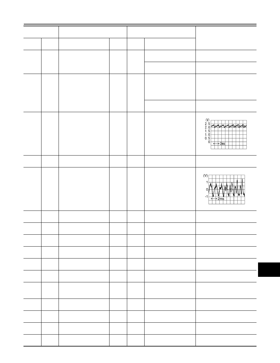
53
(L)
Ground Microphone signal
Input
ON
Speak into microphone
54
(Shield)
—
Microphone signal shield
—
—
—
—
55
(W)
Ground AUX sound signal RH
Input
ON
AUX mode selected.
56
(Shield)
—
AUX sound signal shield
—
—
—
—
58
(B)
Ground Camera detection
—
ON
—
0 V
59
(W)
Ground Camera ground
—
ON
—
0 V
60
(Shield)
—
Camera image signal
Shield
—
—
—
—
61
(L)
Ground
USB D
− signal
(Telematics)
Input/
Output
—
—
—
62
(BR)
Ground
USB V BUS signal
(Telematics)
Output
ON
—
—
63
(V)
—
Manufacturer specific sig-
nal
(Telematics)
—
—
—
—
67
(B)
—
VOICE ground
(Telematics)
—
—
—
—
68
(Y)
Ground
U–VOICE signal
(Telematics)
Output
ON
—
—
69
(R)
Ground
USB D+ signal
(Telematics)
Input/
Output
—
—
—
70
(Shield)
—
USB signal shield
(Telematics)
—
—
—
—
Terminal
(Wire color)
Description
Condition
Reference value
(Approx.)
+
–
Signal name
Input/
Output
Power
switch
Operation
PKIB5037J
SKIB3609E