Nissan Primera P11. Manual - part 169


  Index      Nissan     Nissan Primera P11 (2001 year) - Service and Repair Manual


Search            


Content   ..  167  168  169  170   ..


Nissan Primera P11. Manual - part 169


On Board Diagnosis Logic

NCEC0553

DTC No.

Malfunction is detected when ...

Check Items (Possible Cause)

P0335
0335

I

The 10° signal is not entered to ECM for the first few seconds
during engine cranking.

..........................................................................................................

I

The 10° signal is not entered to ECM during engine running.

..........................................................................................................

I

The 10° signal is not in the normal pattern at each engine
revolution.

I

Harness or connectors
(The crankshaft position sensor (POS) circuit is
open or shorted.)

I

Crankshaft position sensor (POS)

I

Starter motor (Refer to EL section.)

I

Starting system circuit (Refer to EL section.)

I

Dead (Weak) battery

DTC Confirmation Procedure

NCEC0554

NOTE:
If “DTC Confirmation Procedure” has been previously conducted,
always turn ignition switch “OFF” and wait at least 9 seconds
before conducting the next test.
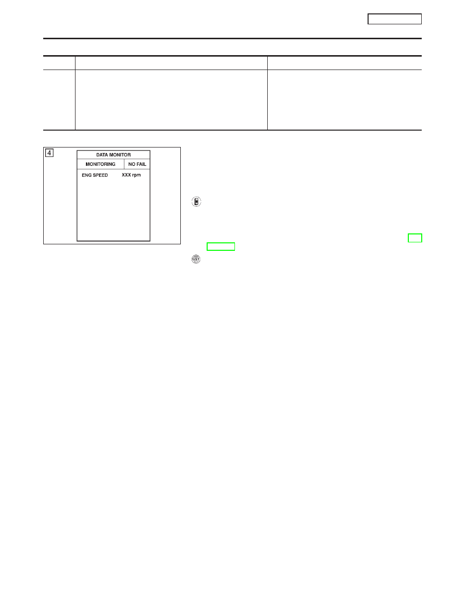
With CONSULT-II

1)

Turn ignition switch “ON” and select “DATA MONITOR” mode
with CONSULT-II.

2)

Start engine and run it for at least 2 seconds at idle speed.

3)

If 1st trip DTC is detected, go to “Diagnostic Procedure”, EC-
QG-235.

With GST

Follow the procedure “With CONSULT-II” above.

NEF068A

DTC P0335 CRANKSHAFT POSITION SENSOR (POS)

QG16

I

18DE

On Board Diagnosis Logic

EC-233

Wiring Diagram

NCEC0555

YEC070A

DTC P0335 CRANKSHAFT POSITION SENSOR (POS)

QG16

I

18DE

Wiring Diagram

EC-234

Diagnostic Procedure

NCEC0556

1

RETIGHTEN GROUND SCREWS

1. Turn ignition switch “OFF”.
2. Loosen and retighten engine ground screws.

SEF994W

©

GO TO 2.

2

CHECK POWER SUPPLY

1. Disconnect crankshaft position sensor harness connector.

SEF117X

2. Turn ignition switch “ON”.
3. Check voltage between terminal 1 and ground with CONSULT-II or tester.

YEC132A

Voltage: Battery voltage

OK or NG

OK

©

GO TO 4.

NG

©

GO TO 3.

DTC P0335 CRANKSHAFT POSITION SENSOR (POS)

QG16

I

18DE

Diagnostic Procedure

EC-235

3

DETECT MALFUNCTIONING PART

Check the following.

I

Harness connectors E90, F73

I

Harness for open or short between crankshaft position sensor and ECM relay

I

Harness for open or short between crankshaft position sensor and ECM

I

ECM relay

©

Repair open circuit or short to ground or short to power in harness or connectors.

4

CHECK INPUT SIGNAL CIRCUIT

1. Disconnect crankshaft position sensor and ECM harness connectors.

SEF117X

2. Check continuity between ECM terminal 85 and crankshaft position sensor harness connector terminal 2.

Refer to wiring diagram.

Continuity should exist.

3. Also check harness for short to ground and short to power.

OK or NG

OK

©

GO TO 5.

NG

©

Repair open circuit or short to ground or short to power in harness or connectors.

5

CHECK GROUND CIRCUIT

1. Reconnect ECM harness connector.
2. Check harness continuity between terminal 3 and engine ground.

Refer to wiring diagram.

Continuity should exist.

3. Also check harness for short to ground and short to power.

OK or NG

OK

©

GO TO 6.

NG

©

Repair open circuit or short to ground or short to power in harness or connectors.

6

CHECK CRANKSHAFT POSITION SENSOR

Refer to “Component Inspection”, EC-QG-237.

OK or NG

OK

©

GO TO 7.

NG

©

Replace crankshaft position sensor.

7

CHECK INTERMITTENT INCIDENT

Perform “TROUBLE DIAGNOSIS FOR INTERMITTENT INCIDENT”, EC-QG-102.

©

INSPECTION END

DTC P0335 CRANKSHAFT POSITION SENSOR (POS)

QG16

I

18DE

Diagnostic Procedure (Cont’d)

EC-236


Content   ..  167  168  169  170   ..