Nissan Frontier D22. Manual - part 177
TROUBLE DIAGNOSIS
BRC-39
[ABS]
C
D
E
G
H
I
J
K
L
M
A
B
BRC
3.
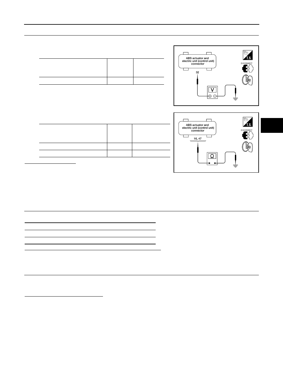
CHECKING SOLENOID POWER AND GROUND
1.
Disconnect ABS actuator and electric unit (control unit) connector E39.
2.
Check voltage between ABS actuator and electric unit (control
unit) harness connector E39 and ground.
3.
Check resistance between ABS actuator and electric unit (con-
trol unit) harness connector E39 and body ground.
Is inspection result OK?
OK
>> Replace ABS actuator and electric unit (control unit).
NG
>> Repair harness or connectors.
Inspection 5 Actuator Motor, Motor Relay, and Circuit
EFS003H3
DTC C1111
Inspection Procedure
1.
CHECKING SELF-DIAGNOSIS RESULTS (1)
Check self-diagnosis results.
Does “PUMP MOTOR” appear in self-diagnosis results display?
YES
>> GO TO 2.
NO
>> Inspection is completed.
2.
CHECKING SELF-DIAGNOSIS RESULTS (2)
1.
Disconnect ABS actuator and electric unit (control unit) connector E39. Then reconnect it securely.
2.
Perform self-diagnosis again.
Do any self-diagnosis items appear?
YES
>> GO TO 3.
NO
>> Poor connection. Repair or replace the applicable connector.
ABS actuator and electric
unit (control unit)
(Harness connector E39)
Body
ground
Voltage (V)
(Approx.)
32 (Y)
—
12
LFIA0148E
ABS actuator and electric
unit (control unit)
(Harness connector E39)
Body
ground
Resistance
value (
Ω)
(Approx.)
16 (B)
—
0
47 (B)
—
0
LFIA0152E
Self-diagnosis results
CONSULT-II display items
PUMP MOTOR