Nissan Frontier D22. Manual - part 150
REMOTE KEYLESS ENTRY SYSTEM
BL-37
C
D
E
F
G
H
J
K
L
M
A
B
BL
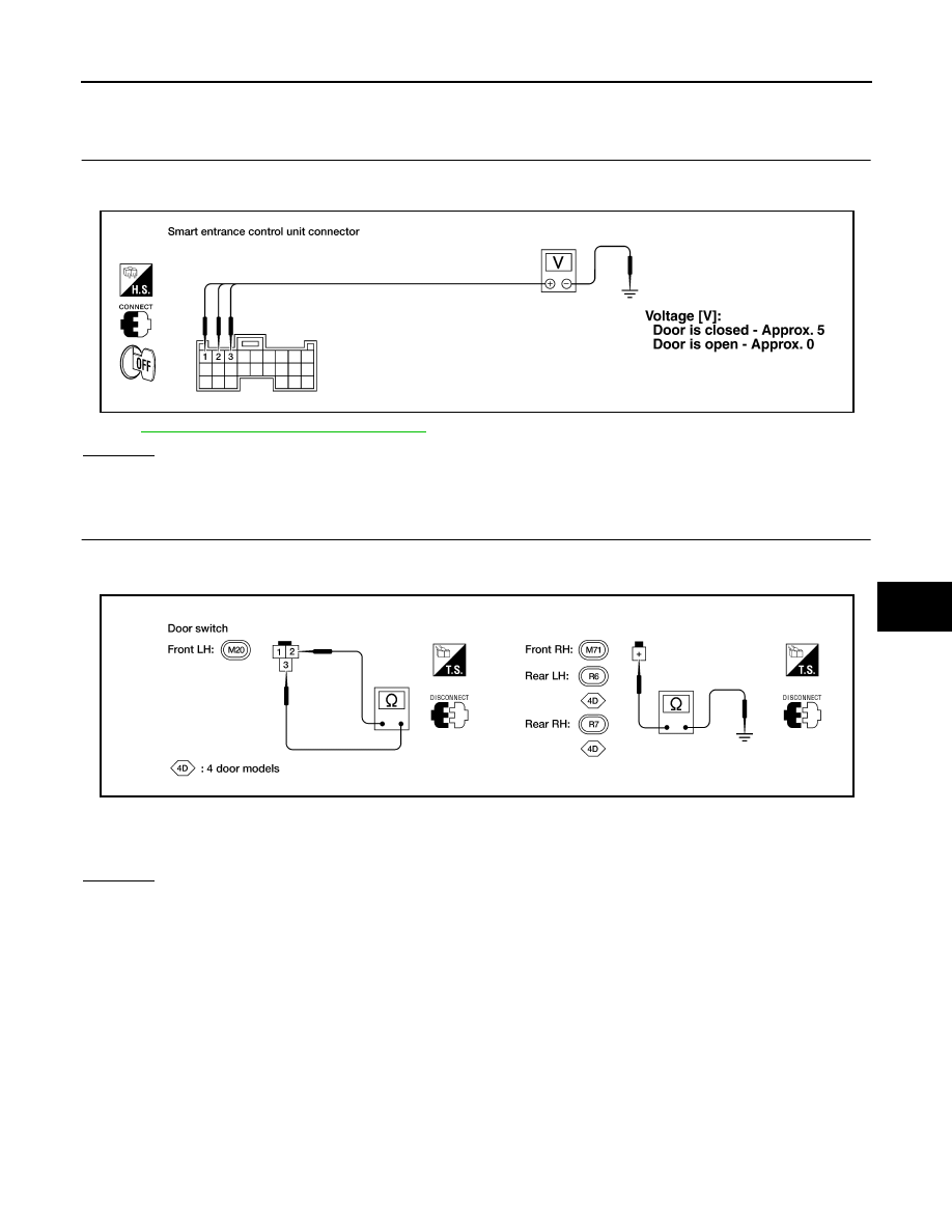
DOOR SWITCH CHECK
1.
CHECK DOOR SWITCH INPUT SIGNAL
Check voltage between smart entrance control unit connector M110 terminals 1 (G/R), 2 (R/B) or 3 (R/B)
(Crew Cab with vehicle security system) and ground.
Refer to
BL-32, "Wiring Diagram — KEYLES —"
.
OK or NG
OK
>> Door switch is OK.
NG
>> GO TO 2.
2.
CHECK DOOR SWITCH
1.
Disconnect door switch harness connector.
2.
Check continuity between door switch terminals.
OK or NG
OK
>> Check the following.
●
Front door switch LH ground circuit or door switch ground condition
●
Harness for open or short between smart entrance control unit and door switch
NG
>> Replace door switch.
WEL517A
Door switch is pressed
: Continuity should not exist.
Door switch is released
: Continuity should exist.
AEL577C