Nissan Frontier D22. Manual - part 89
DTC P1705 THROTTLE POSITION SENSOR
AT-325
[RE4R01A]
D
E
F
G
H
I
J
K
L
M
A
B
AT
Diagnostic Procedure
ECS007NL
1.
CHECK DTC WITH ECM
Perform diagnostic test mode II (self-diagnostic results) for engine control. Refer to
(VG33E only) or
(VG33ER only), “Malfunction Indicator Lamp (MIL)”.
OK or NG
OK
>> GO TO 2.
NG
>> Check throttle position sensor circuit for engine control. Refer to
EC-1350, "DTC P0121 TP SENSOR"
2.
CHECK INPUT SIGNAL
With CONSULT-II
1.
Turn ignition switch to ON position.
(Do not start engine.)
2.
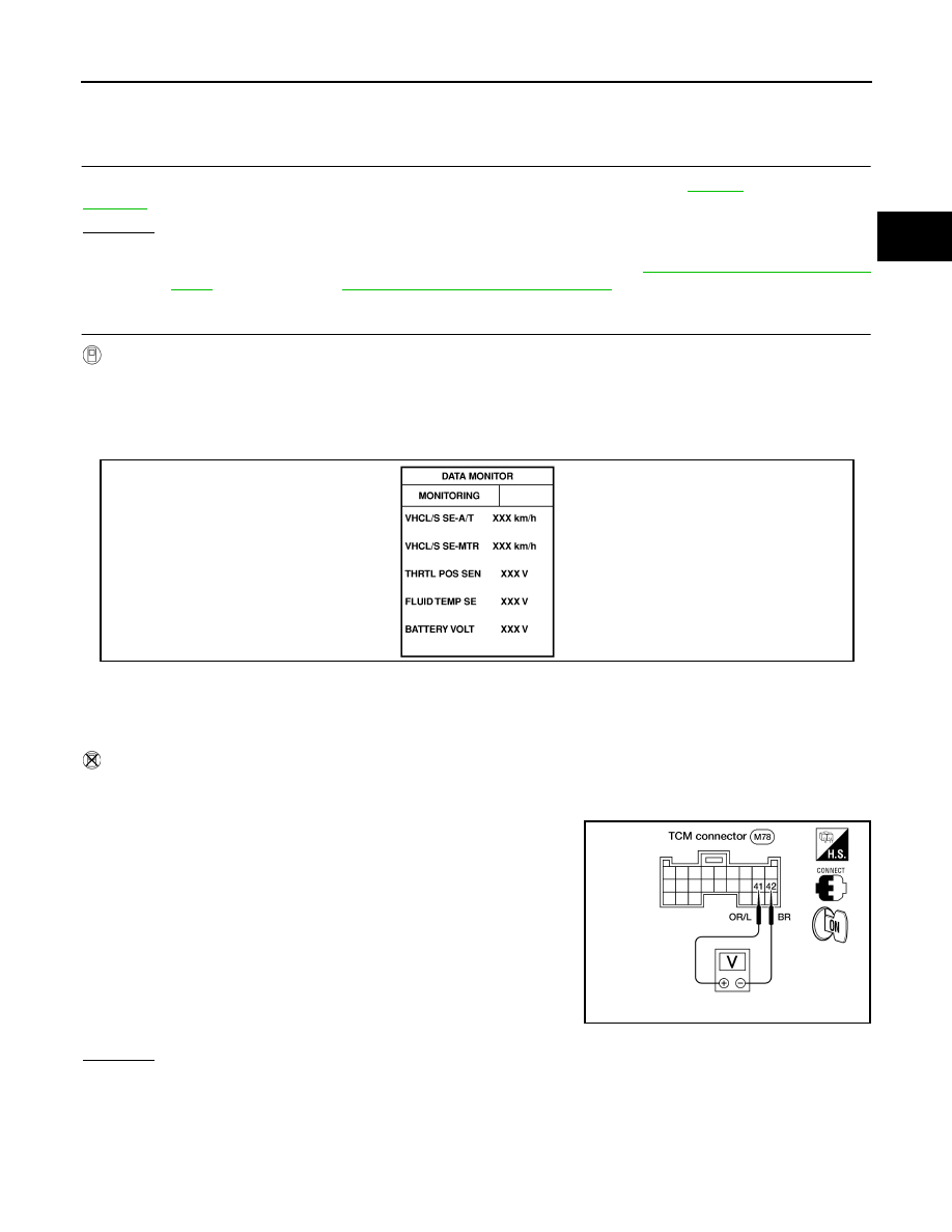
Select “TCM INPUT SIGNALS” in “DATA MONITOR” mode for “A/T” with CONSULT-II.
3.
Read out the value of “THRTL POS SEN”.
Without CONSULT-II
1.
Turn ignition switch to ON position.
(Do not start engine.)
2.
Check voltage between TCM terminals 41 and 42 while acceler-
ator pedal is depressed slowly.
OK or NG
OK (With CONSULT-II)>>GO TO 3.
OK (Without CONSULT-II)>>GO TO 4.
NG
>> Check harness for short or open between ECM and TCM regarding throttle position sensor circuit.
(Main harness)
Voltage
Fully-closed throttle
: Approximately 0.5V
Fully-open throttle
: Approximately 4V
Voltage
Fully-closed throttle
valve
: Approximately 0.5V
Fully-open throttle
valve
: Approximately 4V
(Voltage rises gradually
in response to throttle
position.)
SAT614J
AAT474A