Nissan Xterra. Manual - part 348
EM-20
< PERIODIC MAINTENANCE >
[VQ40DE]
CAMSHAFT VALVE CLEARANCE
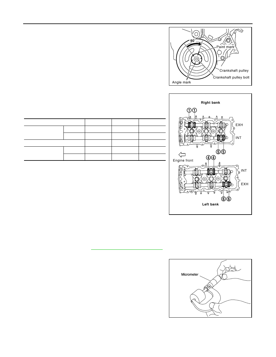
d. Rotate crankshaft by 240
° clockwise (when viewed from engine
front) to align No. 5 cylinder at TDC of compression stroke.
• Measure the valve clearances at locations marked “
×” as
shown in the table below (locations indicated in the illustration)
with feeler gauge.
• No. 5 cylinder at compression TDC
4. For the measured value out of the standard, perform adjustment.
ADJUSTMENT
• Perform adjustment depending on selected head thickness of valve lifter.
1. Measure the valve clearance.
2. Remove camshaft. Refer to
EM-76, "Removal and Installation"
.
3. Remove valve lifters at the locations that are out of the standard.
4. Measure the center thickness of removed valve lifters with
micrometer.
5. Use the equation below to calculate valve lifter thickness for replacement.
PBIC2916E
Measuring position (RH bank)
No. 1 CYL.
No. 3 CYL.
No. 5 CYL.
No. 5 cylinder at
compression TDC
EXH
×
INT
×
Measuring position (LH bank)
No. 2 CYL.
No. 4 CYL.
No. 6 CYL.
No. 5 cylinder at
compression TDC
INT
×
EXH
×
PBIC2056E
KBIA0057E