Nissan PULSAR N13 Series / ASTRA LD Series. Manual - part 56


  Index      Nissan     Nissan PULSAR N13 Series / ASTRA LD Series (1.6 and 1.8 Liter) 1987 – 1991 year - Service Manual


Search            


Content   ..  54  55  56  57   ..


Nissan PULSAR N13 Series / ASTRA LD Series. Manual - part 56


225


BODY


1.    WINDSCREEN AND REAR GLASS


The renewal or replacement of the windscreen 

and the rear glass follows the same basic procedure.


The successful installation and sealing of the 

windscreen or rear glass will depend to a large extent 
on the technical knowledge and experience of the 
operator and it is not recommended that rear glass or 
windscreen replacement be attempted by anyone 
lacking in previous experience.


2.    FRONT DOORS 

INTERIOR HANDLES AND TRIM PANEL


T

Remove and Install


On models with manual windows, carefully 

prise out  the  armrest  trim  plugs and  remove the 
retaining  screws.   Withdraw  the  armrest  from  the 
vehicle. 

On models with power windows, proceed as 

follows: 

Carefully prise out the armrest trim plugs 

and remove the retaining screws. 

Hold the armrest away from the door trim 


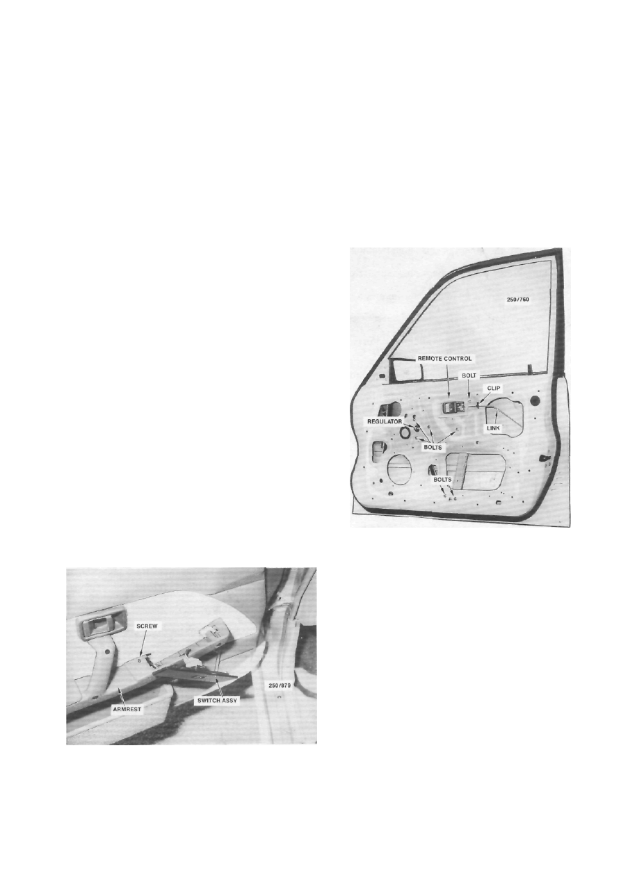
Front door with the trim panel and plastic sealing sheet 

removed. 

panel  as  much  as possible and  lever the window 
switches from the armrest, front end first.


Lift the switch assembly and disconnect the 

wiring connector. 

Remove the hidden screw working through 

the switch aperture. Withdraw the armrest from the 
vehicle. 


Remove the screw retaining the remote con- 

trol assembly escutcheon to the door and remove the 
escutcheon. 

On models with manual windows, lever back 

the regulator handle escutcheon and using a suitable 
wire hook withdraw the handle retaining clip and 
remove the handle and escutcheon. 

Alternatively, a piece of sturdy cloth can be used 

to remove the regulator handle by sliding the cloth 
behind the handle and pulling on each end of the cloth 
in a see-saw action to release the retaining clip.


View of the armrest on models with power windows

showing the hidden screw. 

226


Body


Remove the screws retaining the speaker to 

the trim  panel,  withdraw the  speaker slightly and 
disconnect the wiring connector at the rear. Place the 
speaker to one side clear of the work area. 

On models with a step lamp located in the 

door trim panel, remove the screws, withdraw the step 
lamp and disconnect the wiring connector. 

Using a broad bladed screwdriver, carefully 

lever the trim panel outwards and disengage all the 
retaining clips. When all the clips have been disen- 
gaged maneuver the trim panel from the door. 

Remove  the  screw  retaining the  speaker 

water deflector to the inner door panel and withdraw 
the water deflector. 

Carefully remove the plastic sealing sheet from 

the inner door panel.


Installation is a reversal of the removal procedure 

with attention to the following points:


Ensure that the plastic sealing sheet is cor- 

rectly installed and not torn or damaged. 

Check the trim panel retaining clips and 

renew any damaged clips as necessary. 

On models with manual windows, wind the 

door glass to the closed position, install the 
retaining 
clip to the regulator handle and install the regulator 
handle to correspond with the regulator handle on the 
opposite door. 

DOOR GLASS AND REGULATOR


To Remove and Install


Remove the interior trim panel and handles 

as previously described. 

Lower the door glass to align the lift channel 

with the lower aperture. 

Support  the  door glass  and   remove  the 

retaining screws from the lift channel and door glass. 

Tilt the door glass to disengage it from the 

run channel, then lift the door glass out through the 
door glass opening. 

Remove  the  retaining  bolts  securing the 

regulator assembly to the door panel. On models with 
power  windows,   disconnect  the  wiring  connector. 
Maneuver the regulator assembly from the door 
through the lower aperture. 

Installation is a reversal of the removal procedure 

with attention to the following points:


Ensure that the sliding surfaces are ade- 

quately lubricated with a zinc oxide grease. 

Loosely install the regulator assembly to the 

inner door panel. 

Install the door glass through the door glass 

opening, engage the door glass in the run channel and 
loosely install the retaining screws. 

Tighten  the  regulator  retaining  bolts  and 

operate the door glass a few times up and down to 
ensure that the glass is centralized. Tighten the lift 
channel screws and check the operation of the door 
glass. Adjust as required. 


Dismantled view of the manually operated front door 


window regulator and glass components. 

(5)    Install the plastic sealing sheet, the trim panel 
and the interior handles as previously described.


REMOTE CONTROL AND DOOR LOCK


To Remove and Install


Remove the interior handles, the trim panel 

and the plastic sealing sheet as previously described. 

Remove the screws retaining the door lock to 

the door frame. 

Disconnect the operating links at the door 

lock from the snipper button and the lock cylinder. 
The remote control link can be left connected. On 
models with central locking, disconnect the link from 
the lock actuator. 

Remove the screws securing the remote con- 

trol to the inner door panel, release the link from the 
inner door panel clip and withdraw the remote control 
and door lock assembly from the door. 

Installation is a reversal of the removal procedure 

with attention to the following points:


Ensure that  the exterior handle operates 

correctly and has 0.5-2.0 mm free play at the stepped 
adjuster holder. Adjust the stepped adjuster holder if 
necessary. 

Check the operation of the door lock assem- 

bly before installing the plastic sealing sheet, the trim 
panel and the interior handles as previously described. 

Body


227


Dismantled view of the front door lock components. Dimension A at the stepped adjuster holder should be 

0.5-2.0 mm. Turn the stepped adjuster holder to give the correct free play. 

EXTERIOR DOOR HANDLE


To Remove and Install


Remove the interior handles, the trim panel 

and the plastic sealing sheet as previously described. 

Remove the retaining nuts from inside the 

door panel. Withdraw the handle slightly while ensur- 
ing that the link is sliding out of the lock assembly. 
Maneuver the exterior handle from the vehicle. 

Installation is a reversal of the removal procedure 

with attention to the following points:


Ensure that the exterior handle and seal are 

in a serviceable condition and installed correctly to 
prevent the entry of dust and water. 

Ensure  that   the   exterior  handle   operates 

correctly and has 0.5-2.0 mm free play at the stepped 
adjuster holder. Adjust the stepped adjuster holder if 
necessary. 

Check the operation of the door lock assem- 

bly before installing the plastic sealing sheet, the trim 
panel and the interior handles as previously described. 

LOCK CYLINDER


To Remove and Install


(1)   Remove the interior handles, the trim panel 

and the plastic sealing sheet as previously described.


Wind the door glass up fully and disconnect 

the operating link between the door lock and the lock 
cylinder. 

Using a suitable screwdriver, remove the 

lock cylinder retaining clip and withdraw the lock 
cylinder from the outer door panel. 

Installation is a reversal of the removal 
procedure.


LOCK STRIKER PLATE


To Remove, Install and Adjust


Mark the position of the striker plate on the 

door pillar with a soft lead pencil to facilitate correct 
replacement of the striker plate. 

Remove the retaining screws from the striker 

plate to the door pillar and remove the striker plate. 
Inspect  the  striker plate  for wear and  renew as 
necessary. 

Install the striker plate to the door pillar 

according to the pencil marks made on removal. 

Close the door and observe the alignment 

with the body panel or rear door. If necessary, loosen 
the striker plate retaining screws and move the striker 
plate in or out to achieve a flush fit. 

If the door lifts or drops when the lock 


228


Body


Installed view of the front door lock striker plate. 

engages the striker plate, loosen the retaining screws 
and move the striker plate up or down to eliminate 
the lift or drop.


Installation is a reversal of the removal procedure 

with attention to the following points:


Ensure  that  the  seal   is  in a serviceable 

condition and correctly installed to prevent the entry 
of dust and water. 

Tighten all the screws securely. 

3.    REAR DOORS


INTERIOR HANDLES AND TRIM PANEL


To Remove and Install


On models with manual windows, carefully 

prise out the armrest trim plugs and remove the 
retaining  screws.   Withdraw  the  armrest   from   the 
vehicle. 

On models with power windows, proceed as 

follows: 


Carefully prise out the armrest trim plugs 

and remove the retaining screws. 

Hold the armrest away from the door trim 

panel as much as possible and lever the window 
switches out from the armrest, front end first. 

Lift the switches and disconnect the wiring 

connector. 

Remove the hidden screw, working through 

the switch aperture. Withdraw the armrest from the 
vehicle. 

(3)  Remove the screw retaining the remote con-


EXTERNAL MIRROR 
To Remove and Install


On models with manual mirrors, remove the 

screw retaining the adjuster arm handle and withdraw 
the handle. 

Carefully prise out the cover trim plate and 

remove the retaining screws securing the mirror body 
to the door. 

On models with power mirrors, disconnect 

the mirror wiring connector. 

Withdraw the external mirror and seal from 

the door. 


Rear door with the trim panel and plastic sealing sheet 

removed. 

SNIPPER BUTTON

REMOTE CONTROL


Dismantled view of the power door mirror.


Content   ..  54  55  56  57   ..