Nissan Almera Tino V10 (2001 year). Manual - part 56


  Index      Manuals     Nissan Almera Tino V10 (2001 year) - Service and Repair Manual


Search            copyright infringement  


Content      ..     54      55      56      57     ..


Nissan Almera Tino V10 (2001 year). Manual - part 56


SEF611Y

SEF068XA

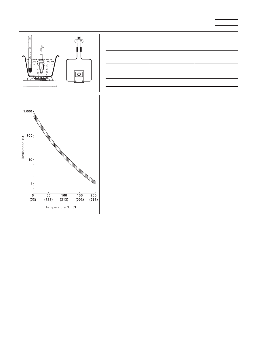
EGR TEMPERATURE SENSOR

NLEC1295S07

Check resistance change and resistance value.
<Reference data>

EGR temperature

°C (°F)

Voltage

V

Resistance

M

0 (32)

4.56

0.62 - 1.05

50 (122)

2.25

0.065 - 0.094

100 (212)

0.59

0.011 - 0.015

If NG, replace EGR temperature sensor.

EGR VOLUME CONTROL SYSTEM (WHERE FITTED)

QG18DE

Component Inspection (Cont’d)

EC-457

Description

NLEC1297

SYSTEM DESCRIPTION

NLEC1297S01

Sensor

Input Signal to ECM

ECM func-

tion

Actuator

Crankshaft position sensor (POS)

Engine speed

EVAP can-
ister purge
control

EVAP canister purge volume
control solenoid valve

Camshaft position sensor (PHASE)

Engine speed and cylinder number

Mass air flow sensor

Amount of intake air

Engine coolant temperature sensor

Engine coolant temperature

Battery

Battery voltage

Ignition switch

Start signal

Closed throttle position switch

Closed throttle position

Throttle position sensor

Throttle position

Heated oxygen sensor 1 (front)

Density of oxygen in exhaust gas
(Mixture ratio feedback signal)

Vehicle speed sensor

Vehicle speed

This system controls flow rate of fuel vapor from the EVAP canis-
ter. The opening of the vapor by-pass passage in the EVAP canis-
ter purge volume control solenoid valve changes to control the flow
rate. The EVAP canister purge volume control solenoid valve
repeats ON/OFF operation according to the signal sent from the
ECM. The opening of the valve varies for optimum engine control.
The optimum value stored in the ECM is determined by consider-
ing various engine conditions. When the engine is operating, the
flow rate of fuel vapor from the EVAP canister is regulated as the
air flow changes.

SEF337U

COMPONENT DESCRIPTION

NLEC1297S02

The EVAP canister purge volume control solenoid valve uses a
ON/OFF duty to control the flow rate of fuel vapor from the EVAP
canister. The EVAP canister purge volume control solenoid valve
is moved by ON/OFF pulses from the ECM. The longer the ON
pulse, the greater the amount of fuel vapor that will flow through the
valve.

CONSULT-II Reference Value in Data Monitor
Mode

NLEC1298

MONITOR ITEM

CONDITION

SPECIFICATION

PURG VOL C/V

+

Engine: After warming up

+

No-load

Idle

0%

Revving engine

EVAP CANISTER PURGE VOLUME CONTROL

SOLENOID VALVE

QG18DE

Description

EC-458

ECM Terminals and Reference Value

=NLEC1299

Specification data are reference values and are measured between each terminal and ground.

CAUTION:

Do not use ECM ground terminals when measuring input/output voltage. Doing so may result in dam-
age to the ECM’s transistor. Use a ground other than ECM terminals, such as the ground.

TER-

MINAL

NO.

WIRE

COLOR

ITEM

CONDITION

DATA (DC Voltage)

14

GY/L

EVAP canister purge vol-
ume control solenoid valve

[Engine is running]

+

Warm-up condition

+

Idle speed

BATTERY VOLTAGE
(11 - 14V)

[Engine is running]

+

Warm-up condition

+

2,000 rpm

5 - 12V

SEF975W

EVAP CANISTER PURGE VOLUME CONTROL

SOLENOID VALVE

QG18DE

ECM Terminals and Reference Value

EC-459

Wiring Diagram

NLEC1302

MODELS WITH ECM IN ENGINE COMPARTMENT

NLEC1302S01

YEC751

EVAP CANISTER PURGE VOLUME CONTROL

SOLENOID VALVE

QG18DE

Wiring Diagram

EC-460

MODELS WITH ECM IN CABIN

NLEC1302S02

YEC898

EVAP CANISTER PURGE VOLUME CONTROL

SOLENOID VALVE

QG18DE

Wiring Diagram (Cont’d)

EC-461

Diagnostic Procedure

NLEC1303

1

INSPECTION START

Do you have CONSULT-II?

Yes or No

Yes

©

GO TO 2.

No

©

GO TO 3.

2

CHECK EVAP CANISTER PURGE VOLUME CONTROL SOLENOID VALVE CONTROL FUNCTION

With CONSULT-II

1. Turn ignition switch “OFF”.
2. Disconnect the EVAP purge hose connected to the EVAP canister purge volume control solenoid valve at the EVAP

canister.

3. Turn ignition switch “ON” and select “PURG VOL CONT/V” in “ACTIVE TEST” mode with CONSULT-II.
4. Start engine and let it idle.
5. Change the valve opening percentage touching “Qu” and “Qd” and check for vacuum existence under the following

conditions.

SEF156Z

OK or NG

OK

©

GO TO 4.

NG

©

GO TO 5.

EVAP CANISTER PURGE VOLUME CONTROL

SOLENOID VALVE

QG18DE

Diagnostic Procedure

EC-462

3

CHECK EVAP CANISTER PURGE VOLUME CONTROL SOLENOID VALVE CONTROL FUNCTION

Without CONSULT-II

1. Start engine and warm it up to normal operating temperature.
2. Turn ignition switch “OFF”.
3. Disconnect the EVAP purge hose connected to the EVAP canister purge volume control solenoid valve at the EVAP

canister.

4. Start engine and let it idle for at least 90 seconds.
5. Check for vacuum existence at the EVAP purge hose under the following conditions.

SEF760Z

OK or NG

OK

©

GO TO 4.

NG

©

GO TO 5.

4

CHECK EVAP CANISTER

1. Turn ignition switch “OFF”.
2. Remove EVAP canister.
3. Block port B of EVAP canister.
4. Blow air through port A orally, and confirm that air flows freely through port C with check valve resistance.
5. Block port A of EVAP canister.
6. Blow air through port B orally, and confirm that air flows freely through port C.

SEF917W

OK or NG

OK

©

INSPECTION END

NG

©

Replace EVAP canister.

EVAP CANISTER PURGE VOLUME CONTROL

SOLENOID VALVE

QG18DE

Diagnostic Procedure (Cont’d)

EC-463

5

CHECK POWER SUPPLY

1. Turn ignition switch “OFF”.
2. Disconnect EVAP canister purge volume control solenoid valve harness connector.

SEF076X

3. Turn ignition switch “ON”.
4. Check voltage between terminals 1 and engine ground with CONSULT-II or tester.

SEF606Y

OK or NG

OK

©

GO TO 7.

NG

©

GO TO 6.

6

DETECT MALFUNCTIONING PART

Check the following.

+

Harness connectors E75, F35 (where fitted)

+

Harness connectors M72, F44 (where fitted)

+

10A fuse

+

Harness for open or short between EVAP canister purge volume control solenoid valve and fuse

©

Repair harness or connectors.

7

CHECK OUTPUT SIGNAL CIRCUIT

1. Turn ignition switch “OFF”.
2. Disconnect ECM harness connector.
3. Check harness continuity between ECM terminal 14 and terminal 2.

Refer to wiring diagram.

Continuity should exist.

4. Also check harness for short to ground and short to power.

OK or NG

OK

©

GO TO 8.

NG

©

Repair open circuit or short to ground or short to power in harness or connectors.

EVAP CANISTER PURGE VOLUME CONTROL

SOLENOID VALVE

QG18DE

Diagnostic Procedure (Cont’d)

EC-464

8

CHECK EVAP CANISTER PURGE VOLUME CONTROL SOLENOID VALVE

Refer to “Component Inspection” EC-465.

OK or NG

OK

©

GO TO 9.

NG

©

Replace EVAP canister purge volume control solenoid valve.

9

CHECK INTERMITTENT INCIDENT

Perform “TROUBLE DIAGNOSIS FOR INTERMITTENT INCIDENT”, EC-145.

©

INSPECTION END

SEF677Y

SEF661U

Component Inspection

NLEC1304

EVAP CANISTER PURGE VOLUME CONTROL
SOLENOID VALVE

NLEC1304S01

With CONSULT-II

1)

Start engine.

2)

Perform “PURG VOL CONT/V” in “ACTIVE TEST” mode with
CONSULT-II. Check that engine speed varies according to the
valve opening.
If OK, inspection end. If NG, go to following step.

3)

Check air passage continuity.

Condition

PURG VOL CONT/V value

Air passage continuity

between A and B

100.0%

Yes

0.0%

No

If NG, replace the EVAP canister purge volume control sole-
noid valve.

Without CONSULT-II

Check air passage continuity.

Condition

Air passage continuity

between A and B

12V direct current supply between ter-
minals

Yes

No supply

No

If NG, replace the EVAP canister purge volume control solenoid
valve.

EVAP CANISTER PURGE VOLUME CONTROL

SOLENOID VALVE

QG18DE

Diagnostic Procedure (Cont’d)

EC-465

Description

NLEC1305

SYSTEM DESCRIPTION

NLEC1305S01

Sensor

Input Signal to ECM

ECM func-

tion

Actuator

Crankshaft position sensor (POS)

Engine speed

Idle air
control

IACV-AAC valve

Camshaft position sensor (PHASE)

Engine speed and cylinder number

Engine coolant temperature sensor

Engine coolant temperature

Ignition switch

Start signal

Throttle position sensor

Throttle position

PNP switch

Park/Neutral position

Air conditioner switch

Air conditioner operation

Power steering oil pressure switch

Power steering load signal

Battery

Battery voltage

Vehicle speed sensor

Vehicle speed

Cooling fan

Cooling fan operation

Electrical load

Electrical load signal

This system automatically controls engine idle speed to a specified
level. Idle speed is controlled through fine adjustment of the
amount of air which by-passes the throttle valve via IACV-AAC
valve. The IACV-AAC valve changes the opening of the air by-pass
passage to control the amount of auxiliary air. This valve is actu-
ated by a step motor built into the valve, which moves the valve in
the axial direction in steps corresponding to the ECM output sig-
nals. One step of IACV-AAC valve movement causes the respec-
tive opening of the air by-pass passage. (i.e. when the step
advances, the opening is enlarged.) The opening of the valve is
varied to allow for optimum control of the engine idling speed. The
crankshaft position sensor (POS) detects the actual engine speed
and sends a signal to the ECM. The ECM then controls the step
position of the IACV-AAC valve so that engine speed coincides with
the target value memorized in ECM. The target engine speed is the
lowest speed at which the engine can operate steadily. The opti-
mum value stored in the ECM is determined by taking into consid-
eration various engine conditions, such as during warm up,
deceleration, and engine load (air conditioner, power steering, cool-
ing fan operation and electrical load).

SEF937W

COMPONENT DESCRIPTION

NLEC1305S02

IACV-AAC Valve

NLEC1305S0201

The IACV-AAC valve is operated by a step motor for centralized
control of auxiliary air supply. This motor has four winding phases
and is actuated by the output signals of ECM which turns ON and
OFF two windings each in sequence. Each time the IACV-AAC
valve opens or closes to change the auxiliary air quantity, the ECM
sends a pulse signal to the step motor. When no change in the
auxiliary air quantity is needed, the ECM does not issue the pulse
signal. A certain voltage signal is issued so that the valve remains
at that particular opening.

IDLE AIR CONTROL VALVE (IACV) —

AUXILIARY AIR CONTROL (AAC) VALVE

QG18DE

Description

EC-466

CONSULT-II Reference Value in Data Monitor
Mode

NLEC1306

MONITOR ITEM

CONDITION

SPECIFICATION

IACV-AAC/V

+

Engine: After warming up

+

Air conditioner switch: OFF

+

Shift lever: “N”

+

No-load

Idle

5 - 25 steps

2,000 rpm

ECM Terminals and Reference Value

NLEC1307

Specification data are reference values and are measured between each terminal and ground.

CAUTION:

Do not use ECM ground terminals when measuring input/output voltage. Doing so may result in dam-
age to the ECM’s transistor. Use a ground other than ECM terminals, such as the ground.

TER-

MINAL

NO.

WIRE

COLOR

ITEM

CONDITION

DATA (DC Voltage)

6
7
15
16

BR
LG
P
OR

IACV-AAC valve

[Engine is running]

+

Warm-up condition

+

Idle speed

0.1 - 14V

IDLE AIR CONTROL VALVE (IACV) —

AUXILIARY AIR CONTROL (AAC) VALVE

QG18DE

CONSULT-II Reference Value in Data Monitor Mode

EC-467

Wiring Diagram

NLEC1310

MODELS WITH ECM IN ENGINE COMPARTMENT

NLEC1310S01

YEC752

IDLE AIR CONTROL VALVE (IACV) —

AUXILIARY AIR CONTROL (AAC) VALVE

QG18DE

Wiring Diagram

EC-468

MODELS WITH ECM IN CABIN

NLEC1310S02

YEC899

IDLE AIR CONTROL VALVE (IACV) —

AUXILIARY AIR CONTROL (AAC) VALVE

QG18DE

Wiring Diagram (Cont’d)

EC-469

Diagnostic Procedure

NLEC1311

1

CHECK OVERALL FUNCTION

1. Turn ignition switch “OFF”.
2. Read the voltage signal between ECM terminals 6, 7, 15, 16 (IACV-AAC valve signal) and ground with an oscilloscope.
3. Turn ignition switch “ON”, wait at least 5 seconds and then “OFF”.
4. Verify that the oscilloscope screen shows the signal wave as shown below at least once every 10 seconds after turning

ignition switch “OFF”.

SEF756Z

OK or NG

OK

©

INSPECTION END

NG

©

GO TO 2.

2

CHECK POWER SUPPLY

1. Turn ignition switch “OFF”.
2. Disconnect IACV-AAC valve harness connector.

NEF316A

3. Turn ignition switch “ON”.
4. Check voltage between terminal 2, 5 and ground with CONSULT-II or tester.

SEF343X

OK or NG

OK

©

GO TO 4.

NG

©

GO TO 3.

IDLE AIR CONTROL VALVE (IACV) —

AUXILIARY AIR CONTROL (AAC) VALVE

QG18DE

Diagnostic Procedure

EC-470

3

DETECT MALFUNCTIONING PART

Check the following.

+

15A fuse

+

Harness connectors E76, F36

+

Harness for open or short between fuse and ECM relay

+

ECM relay

+

Harness for open or short between IACV-AAC and ECM relay

©

Repair harness or connectors or replace fuse or ECM relay.

4

CHECK OUTPUT SIGNAL CIRCUIT

1. Turn ignition switch “OFF”.
2. Disconnect ECM harness connector.
3. Check harness continuity between

ECM terminal 6 and IACV-AAC valve terminal 1,
ECM terminal 7 and IACV-AAC valve terminal 4,
ECM terminal 15 and IACV-AAC valve terminal 3,
ECM terminal 16 and IACV-AAC valve terminal 6.
Refer to wiring diagram.

Continuity should exist.

4. Also check harness for short to ground and short to power.

OK or NG

OK

©

GO TO 5.

NG

©

Repair open circuit or short to ground or short to power in harness or connectors.

5

CHECK AIR CONTROL VALVE (POWER STEERING) OPERATION-I

1. Reconnect the ECM harness connector and IACV-AAC valve harness connector.
2. Disconnect the vacuum hose connected to the air control valve (Power steering) at the intake air duct.
3. Start engine and let it idle.
4. Check vacuum hose for vacuum existence.

SEF162Z

Vacuum does not exist or slightly exist.

OK or NG

OK

©

GO TO 6.

NG

©

Replace air control valve (Power steering).

IDLE AIR CONTROL VALVE (IACV) —

AUXILIARY AIR CONTROL (AAC) VALVE

QG18DE

Diagnostic Procedure (Cont’d)

EC-471

6

CHECK AIR CONTROL VALVE (POWER STEERING) OPERATION-II

Check the vacuum hose for vacuum existence when steering wheel is turned.

SEF162Z

Vacuum should exist.

OK or NG

OK

©

GO TO 9.

NG

©

GO TO 7.

7

CHECK VACUUM PORT

1. Stop engine.
2. Disconnect the vacuum hose connected to the air control valve (Power steering) at the vacuum port.
3. Blow air into vacuum port.
4. Check that air flows freely.

SEF924Y

OK or NG

OK

©

GO TO 8.

NG

©

Repair or clean vacuum port.

IDLE AIR CONTROL VALVE (IACV) —

AUXILIARY AIR CONTROL (AAC) VALVE

QG18DE

Diagnostic Procedure (Cont’d)

EC-472


Content      ..     54      55      56      57     ..