Nissan Almera Tino V10. Manual - part 691
NEL714
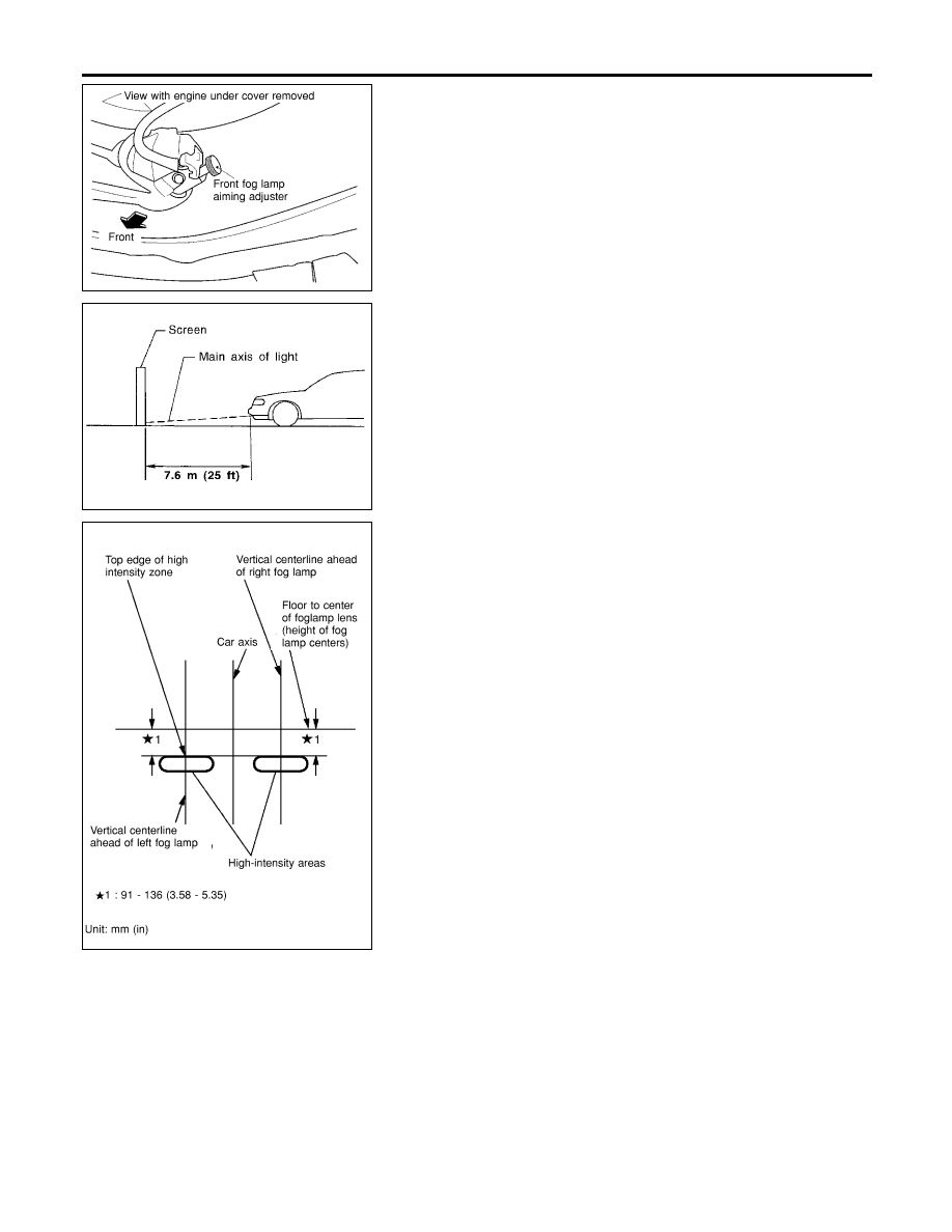
Aiming Adjustment
=NLEL0029
Before performing aiming adjustment, make sure of the following.
1)
Keep all tires inflated to correct pressure.
2)
Place vehicle on level ground.
3)
See that vehicle is unloaded (except for full levels of coolant,
engine oil and fuel, and spare tire, jack, and tools). Have the
driver or equivalent weight placed in driver’s seat.
Adjust aiming in the vertical direction by turning the adjusting
screw.
MEL327G
1.
Set the distance between the screen and the center of the fog
lamp lens as shown at left.
2.
Remove front fog lamp rim. For detail, refer to “BODY END” in
BT section.
3.
Turn front fog lamps ON.
NEL716
4.
Adjust front fog lamps so that the top edge of the high inten-
sity zone is 91 to 136 mm (3.58 to 5.35 in) below the height of
the fog lamp centers as shown at left.
I
When performing adjustment, if necessary, cover the head-
lamps and opposite fog lamp.
FRONT FOG LAMP
Aiming Adjustment
EL-60