Nissan Almera Tino V10. Manual - part 248
NBR423
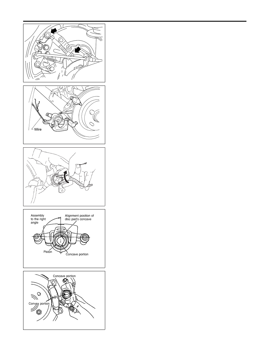
1.
Remove master cylinder reservoir cap.
2.
Remove brake cable lock spring.
3.
Release parking brake control lever, then disconnect cable
from the caliper.
4.
Remove upper pin bolt.
NBR426
5.
Open cylinder body downward. Then remove pads inner and
outer shims.
Standard pad thickness:
9.3 mm (0.366 in)
Pad wear limit:
2.0 mm (0.079 in)
SBR641
6.
When installing new pads, push piston into cylinder body by
gently turning piston clockwise, as shown.
Carefully monitor brake fluid level because brake fluid will
return to reservoir when pushing back piston.
NBR374
7.
Adjust the piston to the right angle as shown in the figure.
NBR375
8.
As shown in the figure, align the piston’s concave to the pad’s
convex, then install the cylinder body to the torque member.
9.
Install brake cable, brake cable mounting bolt, lock spring and
master cylinder reservoir cap.
REAR DISC BRAKE (BALL & RAMP TYPE)
Pad Replacement (Cont’d)
BR-40