Nissan Almera Tino V10. Manual - part 14


  Index      Nissan     Nissan Almera Tino V10 - Service Manual (2003 year)


Search            


Content   ..  12  13  14  15   ..


Nissan Almera Tino V10. Manual - part 14


Inspection and Adjustment

NLCL0006

CLUTCH PEDAL INSPECTION

NLCL0006S04

Pedal Stroke

NLCL0006S0401

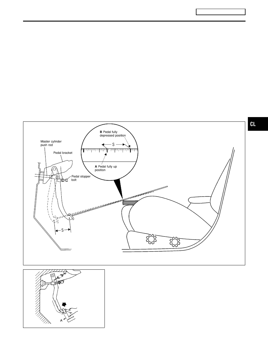
Check clutch pedal stroke by using a 1–meter rule to measure the
total pedal stroke. Place end of rule onto the middle of the clutch
pedal pad. Place a book/clipboard on the driver’s seat to set a ref-
erence point, ensure the book/clipboard does not move during
pedal depression. Mark (A) the pedal fully up position on the rule.
Depress the clutch pedal and mark (B) the rule again next to the
reference point on the book/clipboard. Measure the distance
between the marks (A and B), this is the actual pedal stroke (S).
Check the specified pedal stroke in the table, adjust actual pedal
stroke if necessary (refer to “CLUTCH PEDAL ADJUSTMENT”).
NOTE:

I

Do not use steering wheel as a reference point, angle gives
incorrect reading.

I

Ensure there is no interference between the floor carpet and
clutch pedal when fully depressed.

NCL058

SCL702

Pedal Free Play

NLCL0006S0402

Check pedal free play, if out of specification refer to “CLUTCH
PEDAL ADJUSTMENT”

I

Push on the clutch pedal until resistance is felt, and check the
distance the pedal moves.

GI

MA

EM

LC

EC

FE

MT

AT

AX

SU

BR

ST

RS

BT

HA

SC

EL

IDX

CLUTCH SYSTEM

RS5F70A, RS5F50A

Inspection and Adjustment

CL-9

CLUTCH PEDAL ADJUSTMENT

NLCL0006S01

Pedal Stroke

NLCL0006S0101

1.

Loosen the pedal stopper bolt completely (so there is no con-
tact between pedal and stopper bolt).

2.

Adjust pedal stroke to the specified value with the master cyl-
inder push rod.

3.

Adjust the pedal stopper bolt until it is just in contact with the
pedal, then tighten the lock nut.

4.

Once stroke is set to specification, adjust clutch pedal free
play.

Pedal stroke “S”.
Refer to “SDS”, CL-24.

Pedal Free Play

NLCL0006S0102

1.

Adjust pedal free play to the specified value with the master
cylinder push rod.

2.

Tighten lock nut of the master cylinder push rod.

I

Push on the clutch pedal until resistance is felt, and check the
distance the pedal moves.

Pedal free play “A”.
Refer to “SDS”, CL-24.

SCL838

SCL839

AIR BLEEDING PROCEDURE

NLCL0006S02

1.

Bleed air from clutch operating cylinder according to the fol-
lowing procedure.

I

Carefully monitor fluid level at reservoir during bleeding
operation.

a.

Top up reservoir with recommended brake fluid.

b.

Connect a transparent vinyl tube to air bleeder valve.

c.

Slowly depress the clutch pedal to its full stroke and release it
completely. Repeat this operation several times at 2 to 3 sec-
onds intervals.

d.

Open the air bleeder with the clutch pedal fully depressed.

e.

Close the air bleeder.

f.

Release the clutch pedal and wait at least 5 seconds.

g.

Repeat steps c through f mentioned above, until clear brake
fluid comes out of air bleeder valve.

Air bleeder valve tightening torque:

: 5.9 - 9.8 N·m (0.6 - 1.0 kg-m, 52 - 86 in-lb)

CLUTCH SYSTEM

RS5F70A, RS5F50A

Inspection and Adjustment (Cont’d)

CL-10

Components

NLCL0007

NCL052

NCL053

GI

MA

EM

LC

EC

FE

MT

AT

AX

SU

BR

ST

RS

BT

HA

SC

EL

IDX

CLUTCH MASTER CYLINDER

RS5F70A, RS5F50A

Components

CL-11

Removal

NLCL0008

1.

Drain brake fluid.

CAUTION:

Be careful not to splash brake fluid on painted areas; it may
cause paint damage. If brake fluid is splashed on painted
areas, wash it away with water immediately.
2.

Remove clutch tube using a flare nut wrench.

3.

Remove snap pin between clutch pedal and push rod, and
remove clevis pin.

4.

Unscrew master cylinder assembly mounting nuts and remove
master cylinder assembly from vehicle.

Installation

NLCL0009

1.

Connect clutch tube to master cylinder assembly, and hand-
tighten flare nut.

2.

Install master cylinder assembly to vehicle, and tighten mount-
ing nuts to the specified torque.

: 13 - 16 N·m (1.3 - 1.6 kg-m, 10 - 12 ft-lb)

3.

Tighten clutch tube flare nut using a flare nut torque wrench.

: 15 - 18 N·m (1.5 - 1.8 kg-m, 11 - 13 ft-lb)

4.

After installing clevis pin, install snap pin to connect clutch
pedal to push rod.

5.

After finishing the operation, bleed air from clutch piping con-
nector and operating cylinder. (Refer to “Air Bleeding
Procedure”, CL-10.)

SCL725

Disassembly

NLCL0010

1.

Loosen push rod lock nut A to remove clevis and lock nut A.

2.

Remove dust cover.

3.

Remove stopper ring and stopper, and remove push rod from
cylinder body. During removal, keep push rod depressed, to
prevent piston inside master cylinder from popping out.

4.

Remove piston assembly from cylinder body.

Inspection

NLCL0011

Check the following items, and replace if necessary.

I

Rubbing surface of cylinder and piston, for uneven wear, rust
or damage

I

Piston with piston cup, for wear or damage

I

Return spring, for wear or damage

I

Dust cover, for cracks, deformation or damage

I

Reservoir, for deformation or damage

CLUTCH MASTER CYLINDER

RS5F70A, RS5F50A

Removal

CL-12


Content   ..  12  13  14  15   ..