Nissan GT-R (2007-2014 year). AUDIO, VISUAL & NAVIGATION SYSTEM. Service Manual - part 9
AV
AV CONTROL UNIT
AV-129
< ECU DIAGNOSIS INFORMATION >
[BOSE AUDIO WITH NAVIGATION]
C
D
E
F
G
H
I
J
K
L
M
B
A
O
P
Fail-Safe
INFOID:0000000009163343
When the ambiance temperature becomes extremely low or extremely high, AV control unit displays the mes-
sage and limits the AV control unit function.
FAIL-SAFE CONDITIONS
When the ambiance temperature is
−
20
°
C (
−
4
°
F) or lower, or when it is 70
°
C (158
°
F) or higher
104
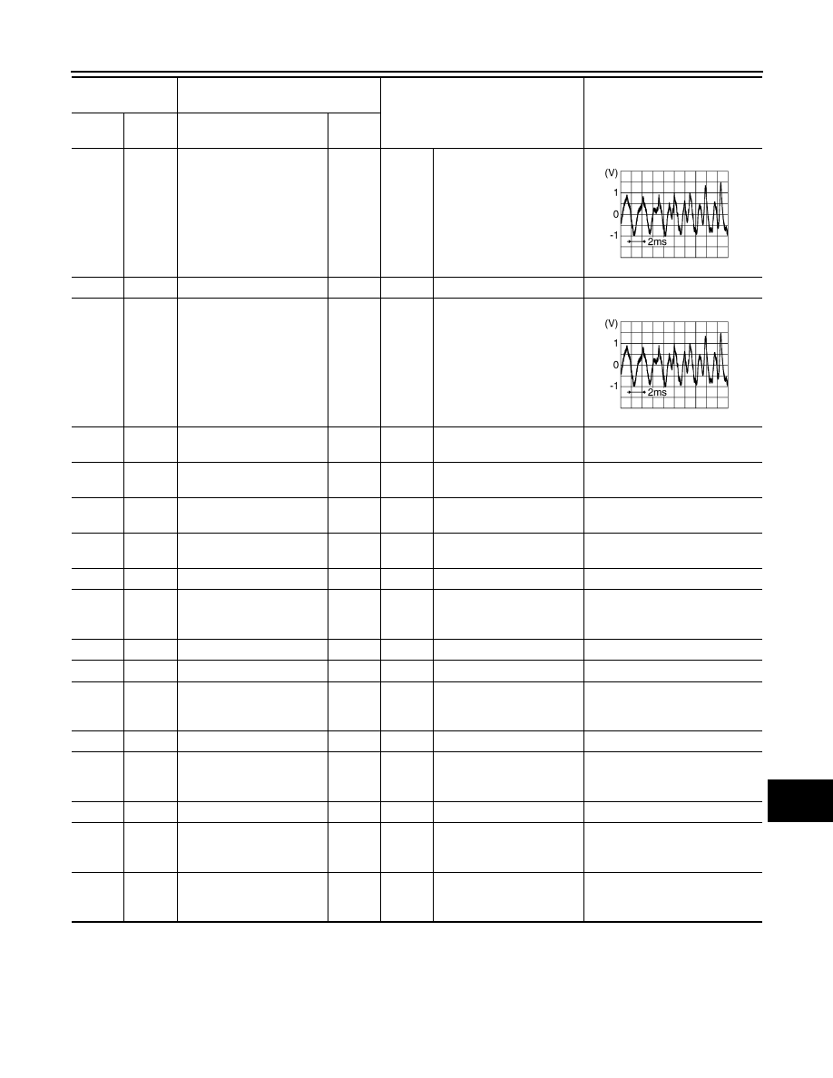
(W)
119
(B)
AUX sound signal LH
Input
Ignition
switch
ON
When AUX mode is select-
ed.
117
—
Shield
—
—
—
—
118
(R)
119
(B)
AUX sound signal RH
Input
Ignition
switch
ON
When AUX mode is select-
ed.
129
(G)
—
USB ground
—
—
—
—
130
(R)
—
USB D
−
—
—
—
—
131
(W)
—
V BUS signal
—
—
—
—
132
(L)
—
USB D+
—
—
—
—
133
—
Shield
—
—
—
—
134
Ground
Antenna amp. ON signal
Output
Ignition
switch
ON
—
12.0 V
135
—
AM–FM main
Input
—
—
—
136
—
FM sub
Input
—
—
—
137
Ground
GPS antenna signal
Input
Ignition
switch
ON
Not connected to GPS an-
tenna connector
5.0 V
138
—
Shield
—
—
—
—
139
Ground
Satellite radio antenna sig-
nal
Input
Ignition
switch
ON
Not connected to satellite
radio antenna connector.
5.0 V
140
—
Shield
—
—
—
—
157
Ground
RGB digital image signal
(+)
Output
Ignition
switch
ON
Not connected connector.
3.3 V
158
Ground
RGB digital image signal
(
−
)
Output
Ignition
switch
ON
Not connected connector.
3.3 V
Terminal
(Wire color)
Description
Condition
Reference value
(Approx.)
+
–
Signal name
Input/
Output
SKIB3609E
SKIB3609E
Revision: 2012 November
2014 GT-R