содержание .. 232 233 234 235 ..
Nissan GT-R. Manual - part 234
PCS
IPDM E/R (INTELLIGENT POWER DISTRIBUTION MODULE ENGINE ROOM)
PCS-17
< REMOVAL AND INSTALLATION >
[IPDM E/R]
C
D
E
F
G
H
I
J
K
L
B
A
O
P
N
REMOVAL AND INSTALLATION
IPDM E/R (INTELLIGENT POWER DISTRIBUTION MODULE ENGINE
ROOM)
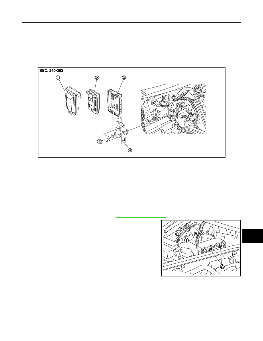
Exploded View
INFOID:0000000009163870
Removal and Installation
INFOID:0000000009163871
CAUTION:
IPDM E/R integrated relays are not serviceable parts, and must not be removed from the unit.
REMOVAL
1.
Remove the battery. Refer to
2.
Remove the cowl top cover (RH). Refer to
.
3.
Pull up the IPDM E/R assembly while pressing the pawls (A) on
the back of the IPDM E/R cover B (1).
1.
IPDM E/R cover A
2.
IPDM E/R
3.
IPDM E/R cover B
4.
Bracket
NNMIA0052ZZ
NNMIA0053ZZ