Nissan GT-R. Manual - part 120


  Главная      Nissan     Nissan GT-R (2007-2014 year) - Service Manual


поиск по сайту            


содержание   ..  118  119  120  121   ..


Nissan GT-R. Manual - part 120


EXT-34

< REMOVAL AND INSTALLATION >

CENTER MUD GUARD

Removal and Installation

INFOID:0000000009161564
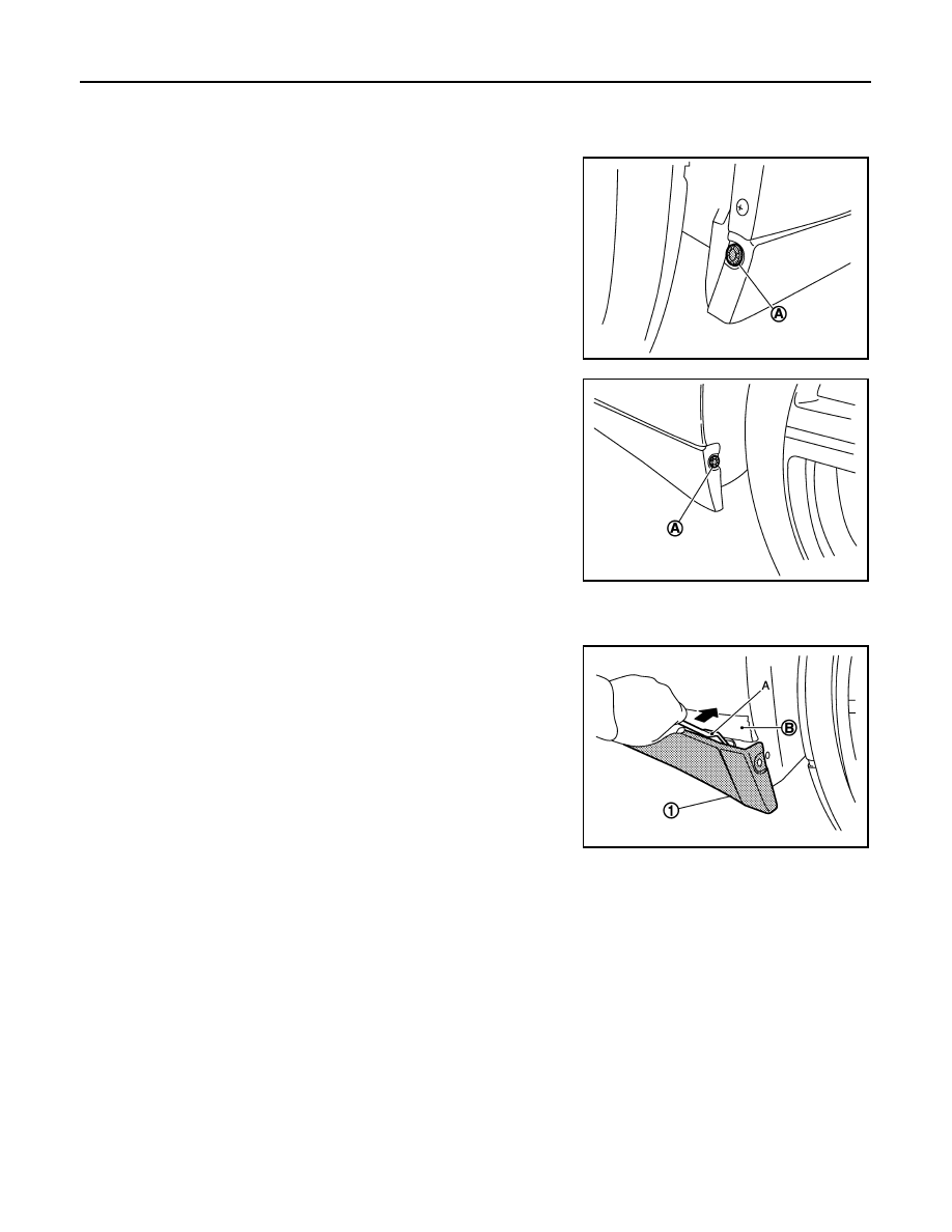
REMOVAL

1.

Remove the clip (A) from the front edge of the center mud
guard. 

2.

Remove the clip (A) from the rear edge of the center mud guard. 

3.

Remove the mounting screws on the center mud guard lower surface. 

4.

Fully open the door. 

5.

Disengage the clips of the center mud guard (1) from vehicle
rear sequentially with the remover tool (A). 

CAUTION:

Apply protective tape (B) to the body side to protect from
damage. 

6.

Remove the center mud guard from the vehicle body. 

7.

Remove the mounting screws after removing the center mud guard, and then remove the front bracket,
center bracket, rear bracket, and wind deflector from the vehicle body. 
NOTE:
The front bracket, center bracket, rear bracket, and wind deflector can be removed as a single part. 

INSTALLATION

Note the following, and install in the reverse order of removal.

CAUTION:

• Check visually the clips for deformation and damage at installation. Replace with new ones if neces-

sary. 

• When installing, check that the clips are accurately aligned with the body side panel, then press in. 

NNKIA0129ZZ

NNKIA0135ZZ

NNKIA0147ZZ

FLOOR SIDE FAIRING

EXT-35

< REMOVAL AND INSTALLATION >

C

D

E

F

G

H

I

J

L

M

A

B

EXT

N

O

P

FLOOR SIDE FAIRING

ENGINE UNDER COVER 

ENGINE UNDER COVER  : Exploded View

INFOID:0000000009161565

NOTE:
This exploded view for VIN < JN1AR54M99M 220041 and VIN < JN1AR54F79M 252231.

NOTE:

1.

Bumper bracket LH

2.

Bumper bracket RH

3.

Bumper fascia

4.

Engine under cover

5.

Hole cover

Refer to 

GI-4, "Components"

 for symbols in the figure. 

NNKIA0103GB

EXT-36

< REMOVAL AND INSTALLATION >

FLOOR SIDE FAIRING

This exploded view for VIN > JN1AR54M99M 220041 and VIN > JN1AR54F79M 252231.

ENGINE UNDER COVER  : Removal and Installation

INFOID:0000000009161566

REMOVAL

1.

Remove the hole covers. 

2.

Remove the clips connecting the engine under cover and the fender protector (front). 

3.

Remove the clips (engine undercover rear edge) connected with the engine under cover. 

4.

Remove the bolts connecting the radiator core support. 

5.

Remove the bolts connecting the bumper brackets (LH,RH). 

6.

Remove the bolts connecting the bumper fascia. 

7.

Pull the engine under cover toward the rear of the vehicle and remove. 

INSTALLATION

Note the following, and install in the reverse order of removal.

CAUTION:

• Visually check the clips for deformation and damage at installation. Replace with new ones if neces-

sary. 

• Always tighten the mounting bolts to the specified torque. 

1.

Bumper bracket LH

2.

Bumper bracket RH

3.

Bumper fascia

4.

Engine under cover

5.

Hole cover

Refer to 

GI-4, "Components"

 for symbols in the figure. 

NNKIA1699GB

FLOOR SIDE FAIRING

EXT-37

< REMOVAL AND INSTALLATION >

C

D

E

F

G

H

I

J

L

M

A

B

EXT

N

O

P

• Be careful to install the hole cover because it may drop in the cover if it is pressed excessively. 

FRONT UNDER COVER

FRONT UNDER COVER : Exploded View

INFOID:0000000009161567

FRONT UNDER COVER : Removal and Installation

INFOID:0000000009161568

REMOVAL

1.

Remove the engine under cover.  Refer to 

EXT-36, "ENGINE UNDER COVER : Removal and Installa-

tion"

(Procedure for VIN <JN1AR54M99M 220041/JN1AR54F79M 252231 only)

2.

Remove the clip connecting the front under cover and the fender protector (LH/RH) (front).  Refer to 

EXT-

29, "FENDER PROTECTOR : Exploded View"

3.

Remove the bolt (front under cover rear edge) tightened together with the floor under cover. 

4.

Remove hole cover (engine under cover rear edge).
(Procedure for VIN>JN1AR54M99M 220041/JN1AR54F79M 252231 only)

1.

Radiator core support assembly

2.

Front under cover

3.

Floor under cover

4.

Side member

 : Vehicle front

Refer to 

GI-4, "Components"

 for symbols in the figure. 

NNKIA0104GB


содержание   ..  118  119  120  121   ..