содержание .. 96 97 98 99 ..
Nissan GT-R. Manual - part 98
TURN SIGNAL AND HAZARD WARNING LAMP SYSTEM
EXL-9
< SYSTEM DESCRIPTION >
[XENON TYPE]
C
D
E
F
G
H
I
J
K
M
A
B
EXL
N
O
P
TURN SIGNAL AND HAZARD WARNING LAMP SYSTEM
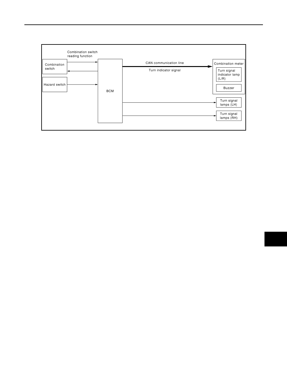
System Diagram
INFOID:0000000009160295
System Description
INFOID:0000000009160296
OUTLINE
Turn signal and the hazard warning lamp is controlled by combination switch reading function and the flasher
control function of BCM.
TURN SIGNAL LAMP OPERATION
• BCM detects the combination switch condition by the combination switch reading function.
• BCM supplies voltage to the right (left) turn signal lamp circuit when the ignition switch is turned ON and the
turn signal switch is in the right (left) position. BCM blinks the turn signal lamp.
HAZARD WARNING LAMP OPERATION
BCM supplies voltage to both turn signal lamp circuit when the hazard switch is turned ON. BCM blinks the
hazard warning lamp.
TURN SIGNAL INDICATOR LAMP AND TURN SIGNAL SOUND OPERATION
• BCM transmits the turn signal indicator lamp signal to the combination meter with CAN communication while
the turn signal lamp and the hazard warning lamp operating.
• Combination meter outputs the turn signal sound with the integrated buzzer while blinking the turn signal
indicator lamp according to the turn signal indicator lamp signal.
HIGH FLASHER OPERATION
• BCM detects the turn signal lamp circuit status by the terminal current value.
• BCM increases the turn signal lamp blinking speed if the bulb or harness open is detected with the turn sig-
nal lamp operating.
NOTE:
The blinking speed is normal while operating the hazard warning lamp.
JPLIA0180GB