Nissan GT-R. Manual - part 63


  Главная      Nissan     Nissan GT-R (2007-2014 year) - Service Manual


поиск по сайту            


содержание   ..  61  62  63  64   ..


Nissan GT-R. Manual - part 63


CHG

L TERMINAL CIRCUIT (OPEN)

CHG-7

< DTC/CIRCUIT DIAGNOSIS >

C

D

E

F

G

H

I

J

K

L

B

A

O

P

N

L TERMINAL CIRCUIT (OPEN)

Description

INFOID:0000000009160048

The “L” terminal circuit controls the charge warning lamp. The charge warning lamp illuminates when the igni-
tion switch is set to ON or START. When the alternator is providing sufficient voltage with the engine running,
the charge warning lamp will go off. If the charge warning lamp illuminates with the engine running, a malfunc-
tion is indicated.

Diagnosis Procedure

INFOID:0000000009160049

1.

CHECK “L” TERMINAL CONNECTION

1.

Turn ignition switch OFF.

2.

Check if “L” terminal is clean and tight.

Is the inspection result normal?

YES

>> GO TO 2.

NO

>> Repair “L” terminal connection. Confirm repair by performing complete Charging system test

using EXP-800 NI or GR8-1200 NI (if available). Refer to the applicable Instruction Manual for
proper testing procedures.

2.

CHECK “L” TERMINAL CIRCUIT (OPEN)

1.

Disconnect alternator connector.

2.

Apply ground to alternator harness connector terminal.

3.

Check condition of the charge warning lamp with the ignition switch in the ON position.

Does it illuminate?

YES

>> “L” terminal circuit is normal.

NO

>> GO TO 3.

3.

CHECK HARNESS CONTINUITY (OPEN CIRCUIT)

1.

Disconnect the battery cable from the negative terminal.

2.

Disconnect the combination meter connector.

3.

Check continuity between alternator harness connector and combination meter harness connector.

Is the inspection result normal?

YES

>> GO TO 4.

NO

>> Repair the harness or connector.

4.

CHECK HARNESS CONTINUITY (OPEN CIRCUIT)

Check continuity between combination meter harness connector and fuse block.

Is the inspection result normal?

YES

>> GO TO 5.

NO

>> Repair the harness.

5.

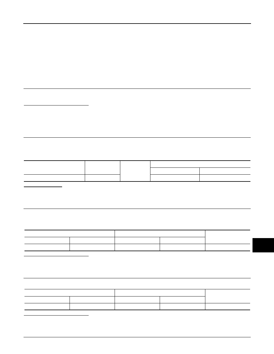
CHECK POWER SUPPLY CIRCUIT

Alternator harness connector

Terminal

Ground

Condition

Ignition switch position

Charge warning lamp

E254

2

ON

 Illuminate

Alternator harness connector

Combination meter harness connector

Continuity

Connector No.

Terminal No.

Connector No.

Terminal No.

E254

2

M53

28

Existed

Combination meter harness connector

Fuse block

Continuity

Connector No.

Terminal No.

Connector No.

Terminal No.

M53

2

M3

12C

Existed

CHG-8

< DTC/CIRCUIT DIAGNOSIS >

L TERMINAL CIRCUIT (OPEN)

1.

Connect the battery cable to the negative terminal.

2.

Check voltage between combination meter harness connector and ground.

Is the inspection result normal?

YES

>> Replace combination meter.

NO

>> Inspect the power supply circuit. Refer to 

PG-17, "Wiring Diagram - IGNITION POWER SUPPLY -

"

.

Terminals

Condition

Voltage (Approx.)

(+)

(–)

Combination meter 

harness connector

Terminal

M53

2

Ground

When the ignition switch is in 

ON position

Battery voltage

CHG

CHARGING SYSTEM

CHG-9

< DTC/CIRCUIT DIAGNOSIS >

C

D

E

F

G

H

I

J

K

L

B

A

O

P

N

CHARGING SYSTEM

Wiring Diagram - CHARGING SYSTEM -

INFOID:0000000009160054

JCMWA6844GB

CHG-10

< PRECAUTION >

PRECAUTIONS

PRECAUTION

PRECAUTIONS

Precaution for Working Range at a Regular Dealership

INFOID:0000000009166612

CAUTION:

The service items unmentioned on this manual are recommended to be performed by a GT-R certified
NISSAN dealer. Because those service items require special equipment and a GT-R certified technical
staff who completed special training.

Precaution for Supplemental Restraint System (SRS) "AIR BAG" and "SEAT BELT 
PRE-TENSIONER"

INFOID:0000000009160056

The Supplemental Restraint System such as “AIR BAG” and “SEAT BELT PRE-TENSIONER”, used along
with a front seat belt, helps to reduce the risk or severity of injury to the driver and front passenger for certain
types of collision. This system includes seat belt switch inputs and dual stage front air bag modules. The SRS
system uses the seat belt switches to determine the front air bag deployment, and may only deploy one front
air bag, depending on the severity of a collision and whether the front occupants are belted or unbelted.
Information necessary to service the system safely is included in the “SRS AIR BAG” and “SEAT BELT” of this
Service Manual.

WARNING:

Always observe the following items for preventing accidental activation.
• To avoid rendering the SRS inoperative, which could increase the risk of personal injury or death in

the event of a collision that would result in air bag inflation, all maintenance must be performed by
an authorized NISSAN/INFINITI dealer.

• Improper maintenance, including incorrect removal and installation of the SRS, can lead to personal

injury caused by unintentional activation of the system. For removal of Spiral Cable and Air Bag
Module, see “SRS AIR BAG”.

• Never use electrical test equipment on any circuit related to the SRS unless instructed to in this Ser-

vice Manual. SRS wiring harnesses can be identified by yellow and/or orange harnesses or harness
connectors.

PRECAUTIONS WHEN USING POWER TOOLS (AIR OR ELECTRIC) AND HAMMERS

WARNING:

Always observe the following items for preventing accidental activation.
• When working near the Air Bag Diagnosis Sensor Unit or other Air Bag System sensors with the

ignition ON or engine running, never use air or electric power tools or strike near the sensor(s) with
a hammer. Heavy vibration could activate the sensor(s) and deploy the air bag(s), possibly causing
serious injury.

• When using air or electric power tools or hammers, always switch the ignition OFF, disconnect the

battery, and wait at least 3 minutes before performing any service.

Precautions Necessary for Steering Wheel Rotation After Battery Disconnection

INFOID:0000000009160057

CAUTION:

Comply with the following cautions to prevent any error and malfunction.
• Before removing and installing any control units, first turn the ignition switch to the LOCK position,

then disconnect both battery cables.

• After finishing work, confirm that all control unit connectors are connected properly, then re-connect

both battery cables.

• Always use CONSULT to perform self-diagnosis as a part of each function inspection after finishing

work. If a DTC is detected, perform trouble diagnosis according to self-diagnosis results.

For vehicle with steering lock unit, if the battery is disconnected or discharged, the steering wheel will lock and
cannot be turned.
If turning the steering wheel is required with the battery disconnected or discharged, follow the operation pro-
cedure below before starting the repair operation.

OPERATION PROCEDURE

1.

Connect both battery cables.


содержание   ..  61  62  63  64   ..