Nissan Pathfinder (2012 year). Manual - part 352
P2122, P2123 APP SENSOR
EC-897
< DTC/CIRCUIT DIAGNOSIS >
[VK56DE]
C
D
E
F
G
H
I
J
K
L
M
A
EC
N
P
O
OK or NG
OK
>> GO TO 2.
NG
>> Repair or replace ground connections.
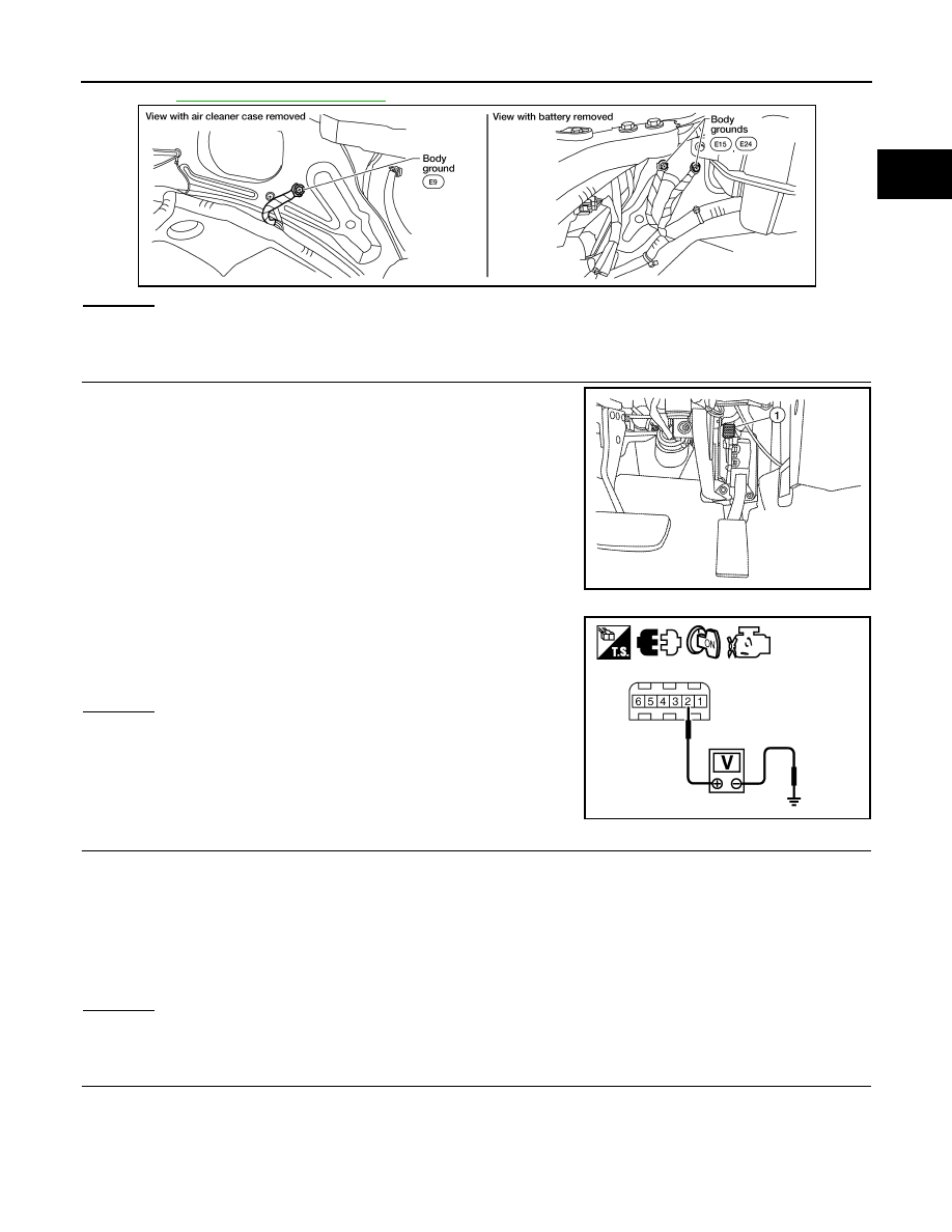
2.
CHECK APP SENSOR 1 POWER SUPPLY CIRCUIT
1. Disconnect accelerator pedal position (APP) sensor (1) harness
connector.
2. Turn ignition switch ON.
3. Check voltage between APP sensor terminal 2 and ground with
CONSULT or tester.
OK or NG
OK
>> GO TO 3.
NG
>> Repair open circuit or short to ground or short to power
in harness or connectors.
3.
CHECK APP SENSOR 1 GROUND CIRCUIT FOR OPEN AND SHORT
1. Turn ignition switch OFF.
2. Disconnect ECM harness connector.
3. Check harness continuity between ECM terminal 82 and APP sensor terminal 4.
Refer to Wiring Diagram.
4. Also check harness for short to ground and short to power.
OK or NG
OK
>> GO TO 4.
NG
>> Repair open circuit or short to ground or short to power in harness or connectors.
4.
CHECK APP SENSOR INPUT SIGNAL CIRCUIT FOR OPEN AND SHORT
1. Check harness continuity between ECM terminal 106 and APP sensor terminal 3.
Refer to Wiring Diagram.
BBIA0539E
AWBIA0079ZZ
Voltage: Approximately 5 V
PBIB2608E
Continuity should exist.
Continuity should exist.
August 2012
2012 Pathfinder