Nissan Pathfinder (2011 year). Manual - part 460
MODE DOOR MOTOR
HAC-143
< DTC/CIRCUIT DIAGNOSIS >
[MANUAL AIR CONDITIONER]
C
D
E
F
G
H
J
K
L
M
A
B
HAC
N
O
P
INSPECTION FLOW
1.
CONFIRM SYMPTOM BY PERFORMING OPERATIONAL CHECK - DISCHARGE AIR
1. Turn blower control dial to 4.
2. Turn the mode dial and check all positions.
3. Confirm that discharge air comes out according to the air distribution table. Refer to
.
NOTE:
Confirm that the compressor clutch is engaged (visual inspection) and intake door position is at FRESH
when DEF (
) or D/F (
) is selected.
Is the inspection result normal?
YES
>> Inspection End.
NO
>> Go to diagnosis procedure. Refer to
HAC-143, "Mode Door Motor (Front) Diagnosis Procedure"
.
Mode Door Motor (Front) Diagnosis Procedure
INFOID:0000000006243707
Regarding Wiring Diagram information, refer to
HAC-172, "Wiring Diagram - Manual"
.
1.
CHECK MODE DOOR MOTOR CIRCUITS FOR OPEN AND SHORT TO GROUND
1. Turn ignition switch OFF.
2. Disconnect the front air control harness connector M52 and the mode door motor harness connector
M144.
3. Check continuity between front air control harness connector M52 terminals 1, 14 and the mode door
motor harness connector M144 terminals 1, 6.
4. Check continuity between front air control harness connector M52 terminals 1, 14 and ground.
Is the inspection result normal?
YES
>> GO TO 2.
NO
>> Repair or replace harness as necessary.
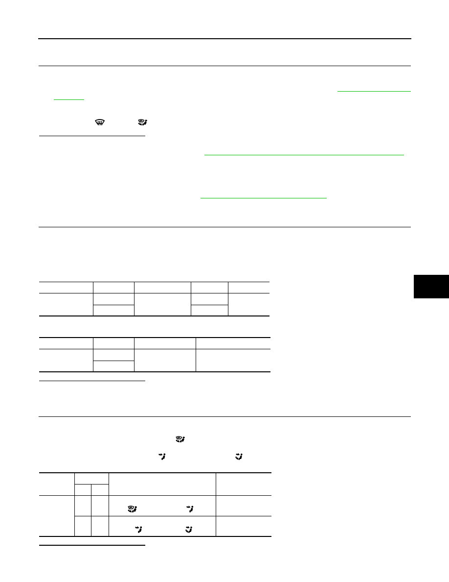
2.
CHECK FRONT AIR CONTROL FOR MODE DOOR MOTOR POWER AND GROUND
1. Reconnect front air control harness connector.
2. Turn ignition switch ON.
3. Rotate the mode switch to the D/F (
) mode.
4. Check voltage between front air control harness connector M52 terminal 1 and terminal 14 while rotating
the mode switch to the VENT (
), and then the B/L (
) mode.
Is the inspection result normal?
YES
>> GO TO 3.
Connector
Terminal
Connector
Terminal
Continuity
M52
1
M144
1
Yes
14
6
Connector
Terminal
—
Continuity
M52
1
Ground
No
14
Connector
Terminals
Condition Voltage
(Approx.)
(+) (-)
M52
1
14
While rotating the mode switch from
D/F (
) mode to VENT (
) mode
Battery voltage
14
1
While rotating the mode switch from
VENT (
) mode to B/L (
) mode
Battery voltage
2011 Pathfinder