Nissan Pathfinder (2011 year). Manual - part 442


  Index      Manuals     Nissan Pathfinder (2011 year) - Service and Repair Manual


Search            copyright infringement  


Content      ..     440      441      442      443     ..


Nissan Pathfinder (2011 year). Manual - part 442


HEATER PUMP

HA-57

< REMOVAL AND INSTALLATION >

C

D

E

F

G

H

J

K

L

M

A

B

HA

N

O

P

HEATER PUMP

Removal and Installation

INFOID:0000000006243612

Heater Pump

NOTE:

• Only the VQ40DE engine is equipped with a heater pump for the rear heater system.

• When removing components such as hoses, tubes/lines, etc., cap or plug openings to prevent fluid from

spilling.

REMOVAL

1. Partially drain the engine cooling system. Refer to 

CO-13, "Changing Engine Coolant"

 (VQ40DE).

2. Disconnect the heater pump electrical connector.
3. Disconnect the two heater hoses.
4. Remove the heater pump from the bracket securing the heater pump to the cowl top.

CAUTION:

Do not disassemble the heater pump, replace the heater pump as an assembly.

INSTALLATION

Installation is in the reverse order of removal.

CAUTION:

• The heater pump rubber mount must be fully seated on the bracket.

• Do not disassemble the heater pump, replace the heater pump as an assembly.
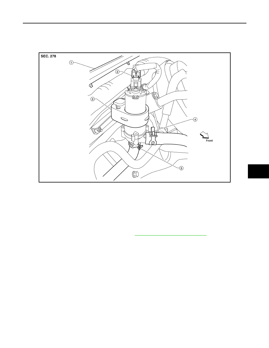
LBIA0414E

1.

Cowl top

2.

Heater pump electrical connector

3.

Heater pump

4.

Heater hose and clamp

5.

Heater hose and clamp

2011 Pathfinder

HA-58

< SERVICE DATA AND SPECIFICATIONS (SDS) 

SERVICE DATA AND SPECIFICATIONS (SDS)

SERVICE DATA AND SPECIFICATIONS (SDS)

SERVICE DATA AND SPECIFICATIONS (SDS)

Service Data and Specification (SDS)

INFOID:0000000006243613

COMPRESSOR

OIL

REFRIGERANT

* : Always check with Parts Department for latest parts information.

Make

ZEXEL VALEO CLIMATE CONTROL*

Model

DKS-17D

Type

Swash plate

Displacement

175.5 cm

3

 (10.7 in

3

) / revolution

Cylinder bore 

×

 stroke

30.5 mm (1.20 in) x 24.0 mm (0.94 in)

Direction of rotation

Clockwise (viewed from drive end)

Drive belt

Poly V

Name

NISSAN A/C System Oil Type S or equivalent

Capacity

With rear A/C

210 m  (7.1 US fl oz, 7.4 Imp fl oz)

Without rear A/C

180 m  (6.1 US fl oz, 6.3 Imp fl oz)

Type

HFC 134a (R-134a)

Capacity

With rear A/C

0.85 

±

 0.05 kg (1.87 

±

 0.11 lb)

Without rear A/C

0.70 

±

 0.05 kg (1.54 

±

 0.11 lb)

2011 Pathfinder

HAC-1

VENTILATION, HEATER & AIR CONDITIONER

C

D

E

F

G

H

J

K

L

M

SECTION 

HAC

A

B

HAC

N

O

P

CONTENTS

HEATER & AIR CONDITIONING CONTROL SYSTEM

AUTOMATIC AIR CONDITIONER

BASIC INSPECTION  ....................................

4

DIAGNOSIS AND REPAIR WORKFLOW  ..........

4

How to Perform Trouble Diagnosis For Quick And 
Accurate Repair  ......................................................
..

4

INSPECTION AND ADJUSTMENT .....................

5

Operational Check (Front) .........................................

5

Operational Check (Rear)  .........................................

6

SYSTEM DESCRIPTION  ..............................

8

FUNCTION INFORMATION  ................................

8

Component Part Location  .........................................

8

Symptom Table  .......................................................

11

REFRIGERATION SYSTEM  ..............................

13

Refrigerant Cycle  ....................................................

13

Refrigerant System Protection ................................

13

AUTOMATIC AIR CONDITIONER SYSTEM  .....

15

Control System Diagram  .........................................

15

Control System Description .....................................

15

Discharge Air Flow (Front)  ......................................

18

Switches And Their Control Function (Front)  ..........

19

Switches And Their Control Function (Rear) ...........

20

DIAGNOSIS SYSTEM (HVAC)  ..........................

21

CONSULT-III Function (HVAC) ...............................

21

DIAGNOSIS SYSTEM (BCM)  ............................

22

COMMON ITEM .........................................................

22

COMMON ITEM : CONSULT-III Function (BCM - 
COMMON ITEM) .....................................................

22

AIR CONDITIONER ...................................................

23

AIR CONDITIONER : CONSULT-III Function 
(BCM - AIR CONDITIONER)  ..................................

23

SELF-DIAGNOSIS FUNCTION ..........................

24

A/C Auto Amp. Self-Diagnosis .................................

24

A/C and AV Switch Assembly Self-Diagnosis  .........

24

A/C System Self-Diagnosis Code Chart  ..................

25

DTC/CIRCUIT DIAGNOSIS  .........................

26

MODE DOOR MOTOR ......................................

26

System Description ..................................................

26

Mode Door Motor (Front) Component Function 
Check ......................................................................

27

Mode Door Motor (Front) Diagnosis Procedure  ......

27

AIR MIX DOOR MOTOR  ...................................

30

System Description ..................................................

30

Air Mix Door Motor (Driver) Component Function 
Check ......................................................................

31

Air Mix Door Motor (Driver) Diagnosis Procedure ....

32

Air Mix Door Motor (Passenger) Component 
Function Check ........................................................

34

Air Mix Door Motor (Passenger) Diagnosis Proce-
dure .........................................................................

34

INTAKE DOOR MOTOR  ...................................

38

System Description ..................................................

38

Intake Door Motor Component Function Check  ......

39

Intake Door Motor Diagnosis Procedure  .................

39

BLOWER MOTOR CONTROL SYSTEM ..........

41

System Description ..................................................

41

Front Blower Motor Component Function Check ....

42

Front Blower Motor Diagnosis Procedure ................

42

Front Blower Motor Component Inspection  .............

46

Rear Blower Motor Description ................................

47

Rear Blower Motor Component Function Check  .....

48

Rear Air Control (Front) Diagnosis Procedure #1 ....

49

Rear Air Control (Rear) Diagnosis Procedure #2 ....

50

Rear Air Control (Rear) Diagnosis Procedure #3 ....

51

Rear Air Control (Rear) Diagnosis Procedure #4 ....

54

Rear Blower Motor And Relay Component Inspec-
tion ...........................................................................

55

REAR AIR CONTROL SYSTEM .......................

57

2011 Pathfinder

HAC-2

Rear Air Control System Description ......................

57

Rear Air Control Component Function Check  ........

57

Rear Air Control (Front) Diagnosis Procedure ........

58

Rear Air Control (Rear) Diagnosis Procedure  ........

62

MAGNET CLUTCH  ............................................

69

System Description .................................................

69

Magnet Clutch Component Function Check ...........

69

Magnet Clutch Diagnosis Procedure  ......................

69

WATER VALVE CIRCUIT ..................................

74

Water Valve Description (VK56DE)  ........................

74

Water Valve Diagnosis Procedure (VK56DE) .........

74

HEATER PUMP  .................................................

76

System Description (VQ40DE)  ...............................

76

Diagnosis Procedure (VQ40DE) .............................

76

Component Inspection (VQ40DE)  ..........................

78

AMBIENT SENSOR ...........................................

79

Component Description  ..........................................

79

Ambient Sensor Diagnosis Procedure ....................

79

Ambient Sensor Component Inspection  .................

80

IN-VEHICLE SENSOR .......................................

82

Component Description  ..........................................

82

In-Vehicle Sensor Diagnosis Procedure .................

82

In-Vehicle Sensor Component Inspection  ..............

84

OPTICAL SENSOR  ...........................................

85

Component Description  ..........................................

85

Optical Sensor Diagnosis Procedure ......................

85

INTAKE SENSOR ..............................................

87

System Description .................................................

87

Intake Sensor Diagnosis Procedure  .......................

87

Intake Sensor Component Inspection  ....................

88

POWER SUPPLY AND GROUND CIRCUIT 
FOR CONTROLLER ..........................................

90

Component Description  ..........................................

90

A/C Auto Amp. Component Function Check  ..........

90

A/C Auto Amp Power and Ground Diagnosis Pro-
cedure ....................................................................
.

91

ECU DIAGNOSIS INFORMATION ..............

93

AIR CONDITIONER CONTROL  ........................

93

A/C Auto Amp. Terminals Reference Values  .........

93

WIRING DIAGRAM  .....................................

95

AIR CONDITIONER CONTROL  ........................

95

Wiring Diagram - Automatic ....................................

95

SYMPTOM DIAGNOSIS  ............................

111

AIR CONDITIONER CONTROL  ......................

111

Symptom Matrix Chart .........................................

111

INSUFFICIENT COOLING ...............................

112

Component Function Check  ..................................

112

Diagnostic Work Flow  ...........................................

113

Performance Chart ................................................

115

Trouble Diagnoses for Abnormal Pressure ...........

116

INSUFFICIENT HEATING  ................................

120

Component Function Check  .................................

120

NOISE ...............................................................

122

Component Function Check  .................................

122

MEMORY FUNCTION DOES NOT OPERATE ..

124

Memory Function Check  .......................................

124

PRECAUTION ...........................................

125

PRECAUTIONS  ................................................

125

Precaution for Supplemental Restraint System 
(SRS) "AIR BAG" and "SEAT BELT PRE-TEN-
SIONER" ...............................................................

125

Precaution Necessary for Steering Wheel Rota-
tion After Battery Disconnect  ................................

125

Working with HFC-134a (R-134a) .........................

126

Precaution for Service Equipment ........................

126

MANUAL AIR CONDITIONER

BASIC INSPECTION .................................

128

DIAGNOSIS AND REPAIR WORKFLOW ........

128

How to Perform Trouble Diagnosis For Quick And 
Accurate Repair  ....................................................

128

INSPECTION AND ADJUSTMENT ..................

129

Operational Check  ................................................

129

SYSTEM DESCRIPTION  ..........................

131

FUNCTION INFORMATION  .............................

131

Component Part Location  .....................................

131

Symptom Table .....................................................

133

REFRIGERATION SYSTEM .............................

134

Refrigerant Cycle  ..................................................

134

Refrigerant System Protection ..............................

134

MANUAL AIR CONDITIONER SYSTEM  .........

136

Control System Diagram .......................................

136

Control System Description ..................................

136

Discharge Air Flow ................................................

138

Switches And Their Control Function ....................

138

DIAGNOSIS SYSTEM (BCM) ...........................

140

COMMON ITEM .......................................................

140

COMMON ITEM : CONSULT-III Function (BCM - 
COMMON ITEM)  ..................................................

140

AIR CONDITIONER .................................................

141

AIR CONDITIONER : CONSULT-III Function 
(BCM - AIR CONDITIONER)  ................................

141

DTC/CIRCUIT DIAGNOSIS .......................

142

MODE DOOR MOTOR  .....................................

142

2011 Pathfinder

HAC-3

C

D

E

F

G

H

J

K

L

M

A

B

HAC

N

O

P

System Description  ...............................................

142

Mode Door Motor (Front) Component Function 
Check ....................................................................

142

Mode Door Motor (Front) Diagnosis Procedure  ....

143

AIR MIX DOOR MOTOR  ..................................

146

System Description  ...............................................

146

Air Mix Door Motor Component Function Check ...

147

Air Mix Door Motor Diagnosis Procedure ..............

147

INTAKE DOOR MOTOR  ..................................

150

System Description  ...............................................

150

Intake Door Motor Component Function Check ....

150

Intake Door Motor Diagnosis Procedure  ...............

151

BLOWER MOTOR ............................................

153

System Description  ...............................................

153

Front Blower Motor Component Function Check ..

153

Front Blower Motor Diagnosis Procedure  .............

154

Front Blower Motor Component Inspection ...........

157

MAGNET CLUTCH ...........................................

160

System Description  ...............................................

160

Magnet Clutch Component Function Check  .........

160

Magnet Clutch Diagnosis Procedure .....................

160

INTAKE SENSOR  ............................................

164

System Description  ...............................................

164

Intake Sensor Diagnosis Procedure ......................

164

Intake Sensor Component Inspection ...................

165

POWER SUPPLY AND GROUND CIRCUIT 
FOR CONTROLLER  ........................................

167

Component Description .........................................

167

Front Air Control Component Function Check  ......

167

Front Air Control Power and Ground Diagnosis 
Procedure ..............................................................

167

ECU DIAGNOSIS INFORMATION ............

169

AIR CONDITIONER CONTROL ......................

169

System Description ................................................

169

System Operation ..................................................

169

Front Air Control Terminals Reference Values ......

170

WIRING DIAGRAM ....................................

172

AIR CONDITIONER CONTROL ......................

172

Wiring Diagram - Manual .......................................

172

SYMPTOM DIAGNOSIS  ............................

178

AIR CONDITIONER CONTROL ......................

178

Symptom Matrix Chart .........................................

178

INSUFFICIENT COOLING  ..............................

179

Component Function Check  ..................................

179

Diagnostic Work Flow ............................................

180

Performance Chart  ................................................

182

Trouble Diagnoses for Abnormal Pressure  ...........

183

INSUFFICIENT HEATING ...............................

187

Component Function Check  ..................................

187

NOISE ..............................................................

189

Component Function Check  ..................................

189

PRECAUTION ............................................

191

PRECAUTIONS ...............................................

191

Precaution for Supplemental Restraint System 
(SRS) "AIR BAG" and "SEAT BELT PRE-TEN-
SIONER" ...............................................................

191

Working with HFC-134a (R-134a) .........................

191

Precaution for Service Equipment  .........................

192

2011 Pathfinder

HAC-4

< BASIC INSPECTION >

[AUTOMATIC AIR CONDITIONER]

DIAGNOSIS AND REPAIR WORKFLOW

BASIC INSPECTION

DIAGNOSIS AND REPAIR WORKFLOW

How to Perform Trouble Diagnosis For Quick And Accurate Repair

INFOID:0000000006243614

WORK FLOW

1.

LISTEN TO CUSTOMER COMPLAINT

Listen to customer complaint. Get detailed information about the conditions and environment when the symp-

tom occurs.

>> GO TO 2

2.

CHECK FOR SERVICE BULLETINS

Check for any service bulletins.

>> GO TO 3.

3.

VERIFY THE SYMPTOM WITH OPERATIONAL CHECK

Verify the symptom with operational check. Refer to 

HAC-5, "Operational Check (Front)"

 or 

HAC-6, "Opera-

tional Check (Rear)"

Is the inspection result normal?

YES

>> GO TO 4

NO

>> GO TO 5

4.

GO TO APPROPRIATE TROUBLE DIAGNOSIS

Go to appropriate trouble diagnosis. Refer to 

HAC-111, "Symptom Matrix Chart"

.

Is the inspection result normal?

>> GO TO 5.

5.

PERFORM THE A/C AUTO AMP SELF-DIAGNOSIS

Perform A/C auto amp. self-diagnosis. Refer to 

HAC-24, "A/C Auto Amp. Self-Diagnosis"

.

>> If any diagnostic trouble codes set. Refer to 

HAC-25, "A/C System Self-Diagnosis Code Chart"

.

>> Confirm the repair by performing operational check. Refer to 

HAC-5, "Operational Check (Front)"

or 

HAC-6, "Operational Check (Rear)"

.

2011 Pathfinder

INSPECTION AND ADJUSTMENT

HAC-5

< BASIC INSPECTION >

[AUTOMATIC AIR CONDITIONER]

C

D

E

F

G

H

J

K

L

M

A

B

HAC

N

O

P

INSPECTION AND ADJUSTMENT

Operational Check (Front)

INFOID:0000000006243615

The purpose of the operational check is to confirm that the system operates properly.

CHECKING MEMORY FUNCTION

1. Set the temperature to 32

°

C (90

°

F).

2. Press the OFF switch.
3. Turn ignition switch OFF.
4. Turn ignition switch ON.

5. Press the AUTO switch.
6. Confirm that the set temperature remains at previous temperature.

7. Press the OFF switch.
If NG, go to trouble diagnosis procedure for 

HAC-124, "Memory Function Check"

.

If OK, continue with next check.

CHECKING BLOWER

1. Press the blower speed control switch (+) once, blower should operate on low speed. The fan display

should have one bar lit (on display).

2. Press the blower speed control switch (+) again, and continue checking blower speed and fan display until

all speeds are checked.

3. Leave blower on maximum speed. 
If NG, go to trouble diagnosis procedure for 

HAC-42, "Front Blower Motor Diagnosis Procedure"

.

If OK, continue with next check.

CHECKING DISCHARGE AIR

1. Press MODE switch four times and the DEF

 switch.

2. Each position indicator should change shape (on display).

3. Confirm that discharge air comes out according to the air distribution table. Refer to 

HAC-18, "Discharge

Air Flow (Front)"

.

Mode door position is checked in the next step.

If NG, go to trouble diagnosis procedure for 

HAC-27, "Mode Door Motor (Front) Diagnosis Procedure"

.

If OK, continue the check.

NOTE:

Confirm that the compressor clutch is engaged (sound or visual inspection) and intake door position is at

fresh when the FOOT, DEF or D/F is selected.

CHECKING RECIRCULATION ( ,   ONLY)

1. Press recirculation (

) switch one time. Recirculation indicator should illuminate.

2. Press recirculation (

) switch one more time. Recirculation indicator should go off.

3. Listen for intake door position change (blower sound should change slightly).
If NG, go to trouble diagnosis procedure for 

HAC-39, "Intake Door Motor Diagnosis Procedure"

.

If OK, continue the check.

NOTE:

Confirm that the compressor clutch is engaged (sound or visual inspection) and intake door position is at fresh
when the FOOT, DEF or D/F is selected. REC (

) is not allowed in DEF (

) D/F (

) or FOOT (

).

CHECKING TEMPERATURE DECREASE

1. Rotate temperature control dial (drive or passenger) counterclockwise until 18

°

C (60

°

F) is displayed.

2. Check for cold air at appropriate discharge air outlets.

Conditions

: Engine running and at normal operating temperature

2011 Pathfinder

HAC-6

< BASIC INSPECTION >

[AUTOMATIC AIR CONDITIONER]

INSPECTION AND ADJUSTMENT

If NG, listen for sound of air mix door motor operation. If OK, go to trouble diagnosis procedure for 

HAC-112,

"Component Function Check"

. If air mix door motor appears to be malfunctioning, go to 

HAC-31, "Air Mix Door

Motor (Driver) Component Function Check"

If OK, continue the check.

CHECKING TEMPERATURE INCREASE

1. Rotate temperature control dial clockwise (drive or passenger) until 32

°

C (90

°

F) is displayed.

2. Check for hot air at appropriate discharge air outlets.
If NG, listen for sound of air mix door motor operation. If OK, go to trouble diagnosis procedure for 

HAC-120,

"Component Function Check"

. If air mix door motor appears to be malfunctioning, go to 

HAC-31, "Air Mix Door

Motor (Driver) Component Function Check"

.  

If OK, continue with next check.

CHECK A/C SWITCH

1. Press A/C switch when AUTO switch is ON, or in manual mode.
2. A/C switch indicator will turn ON.

• Confirm that the compressor clutch engages (sound or visual inspection).

NOTE:

If current mode setting is DEF or D/F, compressor clutch will already be engaged and cannot be turned off.

If NG, go to trouble diagnosis procedure for 

HAC-69, "Magnet Clutch Diagnosis Procedure"

.

If OK, continue with next check.

CHECKING AUTO MODE

1. Press AUTO switch.
2. Display should indicate AUTO.

• If ambient temperature is warm, and selected temperature is cool, confirm that the compressor clutch

engages (sound or visual inspection). (Discharge air and blower speed will depend on ambient, in-vehi-

cle, and set temperatures.)

If NG, go to trouble diagnosis procedure for 

HAC-91, "A/C Auto Amp Power and Ground Diagnosis Proce-

dure"

, then if necessary, trouble diagnosis procedure for  

HAC-69, "Magnet Clutch Diagnosis Procedure"

.

If all operational checks are OK (inspection results are normal), go to malfunction Simulation Tests in  

HAC-4,

"How to Perform Trouble Diagnosis For Quick And Accurate Repair"

 and perform tests as outlined to simulate

driving conditions environment. If symptom appears. Refer to 

HAC-111, "Symptom Matrix Chart"

, and per-

form applicable trouble diagnosis procedures.

Operational Check (Rear)

INFOID:0000000006243616

The purpose of the operational check is to confirm that the system operates properly.

CHECKING REAR BLOWER MOTOR

1. Turn the ignition switch ON.
2. Rotate rear air control (front) blower control dial to low speed.
3. Rotate the blower control dial clockwise and continue checking blower speed until all speeds are checked.
4. Leave blower on maximum speed.
5. Press the REAR CTRL switch from the rear air control (front).
6. Rotate rear air control (rear) blower control dial to low speed.
7. Rotate the blower control dial clockwise and continue checking blower speed until all speeds are checked.
8. Leave blower on maximum speed.
If NG, go to trouble diagnosis procedure for 

HAC-48, "Rear Blower Motor Component Function Check"

.

If OK, continue with next check.

CHECKING REAR TEMPERATURE DECREASE

1. Press the REAR CTRL switch (indicator off).
2. Rotate the rear air control (front) temperature control dial counterclockwise to maximum cold.
3. Check for cold air at appropriate discharge air outlets.

Conditions

: Engine running and at normal operating temperature

2011 Pathfinder


Content      ..     440      441      442      443     ..