Nissan Pathfinder (2011 year). Manual - part 204
DLN-170
< UNIT DISASSEMBLY AND ASSEMBLY >
[TRANSFER: ATX14B]
TRANSFER ASSEMBLY
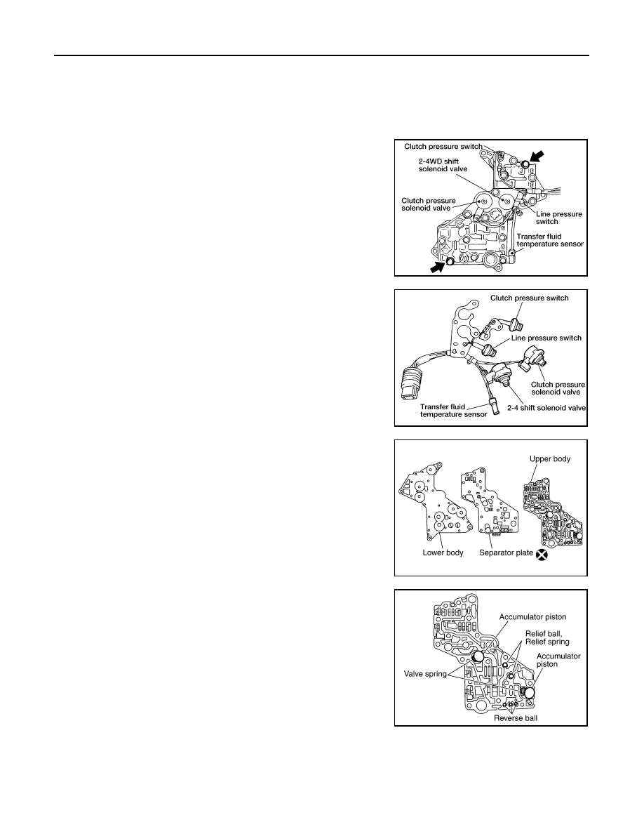
Control Valve Assembly
1. Disassemble the control valve assembly with the following procedure.
CAUTION:
• Do not reuse any part that has been dropped or damaged.
• Make sure valve is assembled in the proper direction.
• Do not use a magnet because residual magnetism stays during disassembly.
a. Remove all the bolts except for the two shown.
b. Remove the following from the control valve assembly:
• Clutch pressure solenoid valve
• Clutch pressure switch
• 2-4WD shift solenoid valve
• Line pressure switch
• Transfer fluid temperature sensor
c.
Remove the O-rings from each solenoid valve, switch and termi-
nal body.
d. Place the control valve with the lower body facing up. Remove
the two bolts, and then remove the lower body and separator
plate from the upper body.
CAUTION:
Do not drop relief balls. Detach lower body carefully.
e. Make sure the reverse balls, relief balls, relief springs, accumu-
lator pistons and valve springs are securely installed as shown,
and remove them.
WDIA0198E
WDIA0199E
WDIA0200E
SDIA2126E
2011 Pathfinder