Nissan Pathfinder (2011 year). Manual - part 66
AV
RGB AREA (YS) SIGNAL CIRCUIT
AV-347
< DTC/CIRCUIT DIAGNOSIS >
[BOSE AUDIO WITH NAVIGATION]
C
D
E
F
G
H
I
J
K
L
M
B
A
O
P
RGB AREA (YS) SIGNAL CIRCUIT
Description
INFOID:0000000006246764
Transmits the display area of RGB image displayed by AV control unit with RGB area (YS) signal to display
unit.
Diagnosis Procedure
INFOID:0000000006246765
Regarding Wiring Diagram information, refer to
AV-385, "Wiring Diagram - With Navigation System"
1.
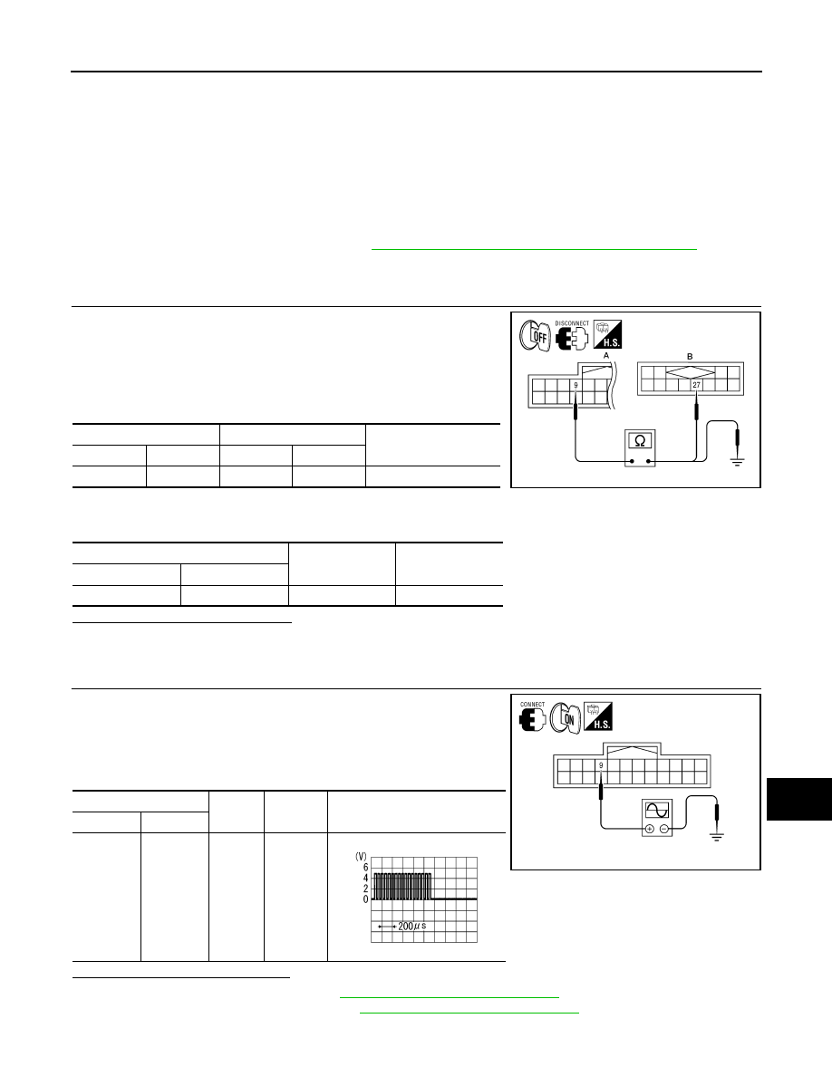
CHECK CONTINUITY RGB AREA (YS) SIGNAL CIRCUIT
1. Turn ignition switch OFF.
2. Disconnect display unit connector M92 and AV control unit con-
nector M37.
3. Check continuity between display unit harness connector M92
(A) terminal 9 and AV control unit harness connector M37 (B)
terminal 27.
4. Check continuity between display unit harness connector M92
(A) terminal 9 and ground.
Are continuity results as specified?
YES
>> GO TO 2
NO
>> Repair harness or connector.
2.
CHECK RGB SYNCHRONIZING SIGNAL
1. Connect display unit connector M92 and AV control unit connec-
tor M37.
2. Turn ignition switch ON.
3. Check signal between display unit harness connector M92 ter-
minal 9 and ground.
Are voltage readings as specified?
YES
>> Replace display unit. Refer to
AV-422, "Removal and Installation"
NO
>> Replace AV control unit. Refer to
AV-420, "Removal and Installation"
.
A
B
Continuity
Connector
Terminal
Connector
Terminal
M92
9
M37
27
Yes
A
—
Continuity
Connector
Terminal
M92
9
Ground
No
AWNIA1793ZZ
(+)
(-)
Condition
Reference signal
Connector
Terminal
M92
9
Ground
Receive
audio sig-
nal
ALNIA0391GB
PKIB4948J
2011 Pathfinder