Nissan Pathfinder (2010 year). Manual - part 622
 

  Index      Manuals     Nissan Pathfinder (2010 year) - Service and Repair Manual


Search            copyright infringement  


Content      ..     620      621      622      623     ..


Nissan Pathfinder (2010 year). Manual - part 622


TM-104

< COMPONENT DIAGNOSIS >

A/T SHIFT LOCK SYSTEM

A/T SHIFT LOCK SYSTEM

Description

INFOID:0000000005501509

Refer to 

TM-32, "System Description"

.

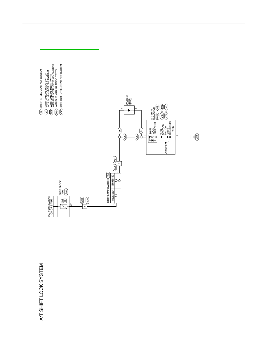
Wiring Diagram - A/T SHIFT LOCK SYSTEM -

INFOID:0000000005258131

ABDWA0176GB

2010 Pathfinder

A/T SHIFT LOCK SYSTEM

TM-105

< COMPONENT DIAGNOSIS >

C

E

F

G

H

I

J

K

L

M

A

B

TM

N

O

P

ABDIA0404GB

2010 Pathfinder

TM-106

< COMPONENT DIAGNOSIS >

A/T SHIFT LOCK SYSTEM

Diagnosis Procedure

INFOID:0000000005258132

Regarding Wiring Diagram information, refer to 

TM-104, "Wiring Diagram - A/T SHIFT LOCK SYSTEM -"

.

1.

CHECK KEY INTERLOCK CABLE

ABDIA0405GB

2010 Pathfinder

A/T SHIFT LOCK SYSTEM

TM-107

< COMPONENT DIAGNOSIS >

C

E

F

G

H

I

J

K

L

M

A

B

TM

N

O

P

Check key interlock cable for damage.
Is the inspection result normal?

YES

>> GO TO 2.

NO

>> Repair key interlock cable. Refer to 

TM-184, "Component"

.

2.

CHECK SELECTOR LEVER

Check selector lever for damage. Refer to 

TM-171, "Inspection and Adjustment"

.

Is the inspection result normal?

YES

>> GO TO 3.

NO

>> Repair selector lever. Refer to 

TM-170, "Exploded view"

.

3.

CHECK INPUT SIGNAL

1. Turn ignition switch ON.

2. Check voltage between A/T shift selector connector terminal 1

and ground.

-

M156 (without manual mode switch)

-

M157 (with manual mode switch without Intelligent Key system)

-

M158 (with manual mode switch and Intelligent Key system)

Is the inspection result normal?

YES

>> GO TO 5.

NO

>> GO TO 4.

4.

CHECK STOP LAMP SWITCH

1. Turn ignition switch OFF.

2. Disconnect stop lamp switch connector.

3. Check continuity between stop lamp switch terminals 3 and 4.

Is the inspection result normal?

YES

>> GO TO 5.

NO

>> Repair or replace damaged parts.

5.

CHECK GROUND CIRCUIT

1. Disconnect A/T shift selector connector.

2. Check continuity between A/T shift selector connector terminal 2

and ground.

-

M156 (without manual mode switch)

-

M157 (with manual mode switch without intelligent key system)

-

M158 (with manual mode switch and intelligent key system)

Is the inspection result normal?

YES

>> GO TO 6.

NO

>> Repair harness or connectors.

6.

CHECK PARK POSITION SWITCH (SHIFT SELECTOR) AND SHIFT LOCK SOLENOID

Brake pedal depressed

: Battery voltage

Brake pedal released

: 0V

AWDIA0583ZZ

Brake pedal depressed

: Continuity should exist.

Brake pedal released

: Continuity should not exist.

AWDIA0419ZZ

Continuity should exist.

AWDIA0584ZZ

2010 Pathfinder

TM-108

< COMPONENT DIAGNOSIS >

A/T SHIFT LOCK SYSTEM

Check continuity between A/T shift selector terminals 1 and 2.

Is the inspection result normal?

YES

>> Inspection End.

NO

>> Replace A/T shift selector. Refer to 

TM-170, "Exploded

view"

.

Selector lever in “P” position

: Continuity should 

exist.

Except above

: Continuity should 

not exist.

AWDIA0585ZZ

2010 Pathfinder

OVERDRIVE CONTROL SWITCH

TM-109

< COMPONENT DIAGNOSIS >

C

E

F

G

H

I

J

K

L

M

A

B

TM

N

O

P

OVERDRIVE CONTROL SWITCH

CONSULT-III Reference Value in Data Monitor Mode

INFOID:0000000005258133

Diagnosis Procedure

INFOID:0000000005258134

1.

CHECK CAN COMMUNICATION LINE

Perform the self-diagnosis. Refer to 

TM-36, "CONSULT-III Function (TRANSMISSION)"

.

Is any malfunction in the CAN communication indicated in the results?

YES

>> Check CAN communication line. Refer to 

TM-46

.

NO

>> GO TO 2.

2.

CHECK OVERDRIVE CONTROL SWITCH CIRCUIT

 With CONSULT-III

1. Turn ignition switch “ON”.

2. Select “ECU INPUT SIGNALS” in “DATA MONITOR” mode for “TRANSMISSION” with CONSULT-III.

3. Read out “OD CONT SW”.

Check the signal of the overdrive control switch is indicated properly.

 Without CONSULT-III

1. Turn ignition switch “ON”. (Do not start engine)

2. Check voltage between A/T control device connector terminal

and ground.

OK or NG

OK

>> GO TO 5.

NG

>> GO TO 3.

3.

CHECK OVERDRIVE CONTROL SWITCH

1. Turn ignition switch “OFF”.

2. Disconnect A/T control device connector.

Item name

Condition

Display value

OD CONT SW

Releasing overdrive control switch

OFF

Holding overdrive control switch

ON

Monitor item

Condition

Display value

OD CONT SW

Releasing overdrive control switch

OFF

Holding overdrive control switch

ON

Item

Connector

Terminal

Condition

Data

(Approx.)

Overdrive 

control switch

M156

7 - Ground

Releasing overdrive 
control switch

Battery 
voltage 

Holding overdrive 
control switch

0V

JSDIA1481ZZ

2010 Pathfinder

TM-110

< COMPONENT DIAGNOSIS >

OVERDRIVE CONTROL SWITCH

3. Check continuity between A/T control device connector termi-

nals.

OK or NG

OK

>> GO TO 4.

NG

>> Repair or replace overdrive control switch.

4.

DETECT MALFUNCTIONING ITEM

Check the following. If any items are damaged, repair or replace damaged parts.

• Harness for short or open between combination meter connector terminal 20 and A/T control device connec-

tor terminal 7.

• Harness for short or open between A/T control device connector terminal 8 and ground.
OK or NG

OK

>> GO TO 5.

NG

>> Repair or replace damaged parts.

5.

CHECK COMBINATION METER

Check the combination meter. Refer to 

MWI-23, "Diagnosis Description"

.

OK or NG

OK

>>

INSPECTION END

NO

>> Repair or replace damaged parts.

Item

Connector

Terminal

Condition

Continuity

Overdrive 

control switch

M156

7 - 8

Releasing over-
drive control switch

No

Holding overdrive 
control switch

Yes

JSDIA1482ZZ

2010 Pathfinder

1ST POSITION SWITCH

TM-111

< COMPONENT DIAGNOSIS >

C

E

F

G

H

I

J

K

L

M

A

B

TM

N

O

P

1ST POSITION SWITCH

CONSULT-III Reference Value in Data Monitor Mode

INFOID:0000000005502469

Diagnosis Procedure

INFOID:0000000005502470

1.

CHECK CAN COMMUNICATION LINE

Perform the self-diagnosis. Refer to 

TM-36, "CONSULT-III Function (TRANSMISSION)"

.

Is any malfunction in the CAN communication indicated in the results?

YES

>> Check CAN communication line. Refer to 

TM-46

.

NO

>> GO TO 2.

2.

CHECK 1ST POSITION SWITCH CIRCUIT

 With CONSULT-III

1. Turn ignition switch “ON”.

2. Select “ECU INPUT SIGNALS” in “DATA MONITOR” mode for “TRANSMISSION” with CONSULT-III.

3. Read out “1 POSITION SW”.

Check the signal of the 1st position switch is indicated properly.

 Without CONSULT-III

1. Turn ignition switch “ON”. (Do not start engine)

2. Check voltage between A/T shift selector connector terminal

and ground.

OK or NG

OK

>> GO TO 5.

NG

>> GO TO 3.

3.

CHECK 1ST POSITION SWITCH

1. Turn ignition switch “OFF”.

2. Disconnect A/T shift selector connector.

Item name

Condition

Display value

1 POSITION SW

When setting selector lever to “1” position.

ON

When setting selector lever to other positions.

OFF

Monitor item

Condition

Display value

1 POSITION SW

When setting selector lever to “1” position.

ON

When setting selector lever to other positions.

OFF

Item

Connector

Terminal

Condition

Data

(Approx.)

1st position 

switch

M156

9 - Ground

When setting selec-
tor lever to “1” posi-
tion.

0V

When setting selec-
tor lever to other po-
sitions.

Battery 
voltage 

JSDIA1483ZZ

2010 Pathfinder


Content      ..     620      621      622      623     ..