Nissan Pathfinder (2010 year). Manual - part 398
EXL-50
< COMPONENT DIAGNOSIS >
TURN SIGNAL LAMP CIRCUIT
Is voltage reading as specified?
YES
>> GO TO 3
NO
>> Replace BCM. Refer to
BCS-59, "Removal and Installation"
3.
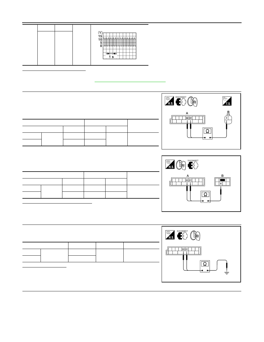
CHECK TURN SIGNAL LAMP CIRCUIT FOR OPEN
1. Turn the ignition switch OFF.
2. Disconnect BCM connector M20.
3. Check continuity between the BCM harness connector M20 (A)
and the front combination lamps harness connector (B).
4. Check continuity between the BCM harness connector M20 (A)
and the rear combination lamp harness connectors (B).
Are continuity results as specified?
YES
>> GO TO 4
NO
>> Repair the harnesses or connectors.
4.
CHECK TURN SIGNAL LAMP SHORT CIRCUIT
Check continuity between the BCM harness connector M20 and
ground.
Does continuity exist?
YES
>> Repair the harnesses or connectors.
NO
>> GO TO 5
5.
CHECK TURN SIGNAL LAMP GROUND CIRCUIT
M20
LH
60
Ground
RH
61
PKID0926E
A
B
Continuity
Connector
Terminal
Connector
Terminal
Front LH
M20
60
E27
3
Yes
Front RH
61
E111
AWLIA1678ZZ
A
B
Continuity
Connector
Terminal
Connector
Terminal
Rear LH
M20
60
B35
4
Yes
Rear RH
61
B105
4
ALLIA0644GB
Connector
Terminal
—
Continuity
LH
M20
60
Ground
No
RH
61
ALLIA0404GB
2010 Pathfinder