Nissan Pathfinder (2009 year). Manual - part 556
POWER SUPPLY AND GROUND CIRCUIT
RF-11
< COMPONENT DIAGNOSIS >
C
D
E
F
G
H
I
J
L
M
A
B
RF
N
O
P
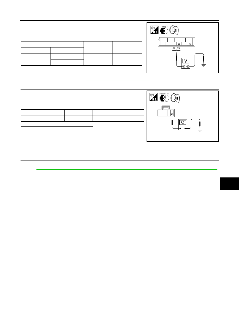
1.
Connect BCM connector M20.
2.
Turn ignition switch ON.
3.
Check voltage between BCM connector M20 and ground.
Is the voltage reading as specified?
YES
>> Check condition of harness and connector.
NO
>> Replace BCM. Refer to
BCS-59, "Removal and Installation"
4.
CHECK GROUND CIRCUIT
1.
Turn ignition switch OFF.
2.
Check continuity between sunroof motor assembly connector
B83 terminal 10 and ground.
Is the continuity test result as specified?
YES
>> Power supply and ground circuits are OK.
NO
>> Repair or replace harness.
SUNROOF MOTOR ASSEMBLY : Special Repair Requirement
INFOID:0000000003938814
1.
PERFORM INITIALIZATION PROCEDURE
Perform initialization procedure.
Refer to
RF-5, "ADDITIONAL SERVICE WHEN REPLACING CONTROL UNIT : Special Repair Requirement"
.
Does the sunroof motor assembly operate properly?
YES
>> Repair is complete.
NO
>> Check fitting adjustment.
(+)
(–)
Voltage
Connector
Terminal
M20
68
Ground
Battery voltage
70
AWKIA1483ZZ
Connector
Terminal
—
Continuity
B83
10
Ground
Yes
ALKIA1178GB
2009 Pathfinder