Nissan Pathfinder (2009 year). Manual - part 503


  Index      Manuals     Nissan Pathfinder (2009 year) - Service and Repair Manual


Search            copyright infringement  


Content      ..     501      502      503      504     ..


Nissan Pathfinder (2009 year). Manual - part 503


OIL PUMP

LU-15

< DISASSEMBLY AND ASSEMBLY >

[VQ40DE]

C

D

E

F

G

H

I

J

K

L

M

A

LU

N

P

O

DISASSEMBLY AND ASSEMBLY

OIL PUMP

Disassembly and Assembly

INFOID:0000000003939438

DISASSEMBLY

1.

Remove oil pump cover.

2.

Remove inner rotor and outer rotor from oil pump body.

3.

Remove the regulator valve plug, regulator valve spring and regulator valve.

INSPECTION AFTER DISASSEMBLY 

Clearance of Oil Pump Parts

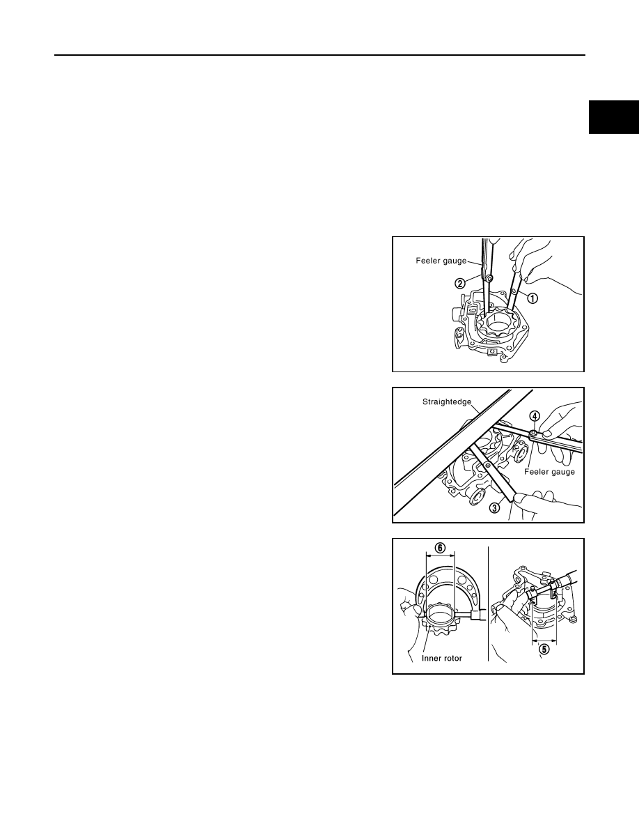
• Measure radial clearance using a suitable tool.

• Measure side clearance using suitable tools.

• Calculate the clearance between inner rotor and oil pump body as

follows.

1.

Measure the inner diameter of oil pump body to brazed portion
(position 5) using suitable tool.

2.

Measure the outer diameter of protruded portion of inner rotor
(position 6) using suitable tool.

3.

Calculate the clearance using the following formula.
• (Clearance) = (Inner diameter of oil pump body) - (Outer diameter of inner rotor)

Regulator Valve Clearance

Body to outer rotor (position 1)

: 0.120 - 0.195 mm (0.0047 - 0.0077 in)

Inner rotor to outer rotor tip (position 2)

: 0.060 - 0.160 mm (0.0024 - 0.0063 in)

PBIC2827E

Body to inner rotor (position 3)

: 0.030 - 0.070 mm (0.0012 - 0.0028 in)

Body to outer rotor (position 4)

: 0.050 - 0.090 mm (0.0020 - 0.0035 in)

PBIC2828E

PBIC0821E

Inner rotor to brazed portion of housing 
clearance

: 0.045 - 0.091 mm (0.0018 - 0.0036 in)

2009 Pathfinder

LU-16

< DISASSEMBLY AND ASSEMBLY >

[VQ40DE]

OIL PUMP

Check regulator valve to oil pump cover clearance using the following formula.
• (Clearance) = D

1

 (Valve hole diameter) - D

2

 (Outer Diameter of

valve)

CAUTION:

• Coat regulator valve with engine oil.
• Check that it falls smoothly into the regulator valve hole by its

own weight.

ASSEMBLY

Installation is in the reverse order of removal.
NOTE:
Install oil pump inner rotor with the grooved face and oil pump outer
rotor with the punch mark to oil pump cover side.

Regulator valve to oil pump cover

: 0.025 - 0.070 mm (0.0010 - 0.0028 in)

PBIC2829E

PBIC2830E

2009 Pathfinder

SERVICE DATA AND SPECIFICATIONS (SDS)

LU-17

< SERVICE DATA AND SPECIFICATIONS (SDS) 

[VQ40DE]

C

D

E

F

G

H

I

J

K

L

M

A

LU

N

P

O

SERVICE DATA AND SPECIFICATIONS (SDS)

SERVICE DATA AND SPECIFICATIONS (SDS)

Standard and Limit

INFOID:0000000003939439

OIL PRESSURE

Unit: kPa (kg/cm

2

, psi)

*: Engine oil temperature at 80

°

C (176

°

F) 

OIL PUMP

Unit: mm (in)

REGULATOR VALVE

Unit: mm (in)

ENGINE OIL CAPACITY (APPROXIMATE)

Unit: 

 (US qt, Imp qt)

Engine speed

rpm 

Approximate discharge pressure*


Idle speed

More than 98 (1.0, 14)

2,000

More than 294 (3.0, 43) 

Body to outer rotor 

0.120 - 0.195 (0.0047 - 0.0077)

Inner rotor to outer rotor tip 

0.060 - 0.160 (0.0024 - 0.0063)

Body to inner rotor 

0.030 - 0.070 (0.0012 - 0.0028)

Body to outer rotor 

0.050 - 0.090 (0.0020 - 0.0035)

Inner rotor to brazed portion of housing 

0.045 - 0.091 (0.0018 - 0.0036)

Regulator valve to oil pump cover

0.025 - 0.070 (0.0010 - 0.0028)

Drain and refill

With oil filter change

5.1 (5-3/8, 4-1/2)

Without oil filter change

4.8 (5-1/8, 4-1/4)

Dry engine (Overhaul)

6.3 (6-5/8, 5-1/2)               

2009 Pathfinder

LU-18

< PRECAUTION >

[VK56DE]

PRECAUTIONS

PRECAUTION

PRECAUTIONS

Precaution for Supplemental Restraint System (SRS) "AIR BAG" and "SEAT BELT 
PRE-TENSIONER"

INFOID:0000000003939440

The Supplemental Restraint System such as “AIR BAG” and “SEAT BELT PRE-TENSIONER”, used along
with a front seat belt, helps to reduce the risk or severity of injury to the driver and front passenger for certain
types of collision. This system includes seat belt switch inputs and dual stage front air bag modules. The SRS
system uses the seat belt switches to determine the front air bag deployment, and may only deploy one front
air bag, depending on the severity of a collision and whether the front occupants are belted or unbelted.
Information necessary to service the system safely is included in the SR and SB section of this Service Man-
ual.

WARNING:

• To avoid rendering the SRS inoperative, which could increase the risk of personal injury or death in

the event of a collision which would result in air bag inflation, all maintenance must be performed by
an authorized NISSAN/INFINITI dealer.

• Improper maintenance, including incorrect removal and installation of the SRS, can lead to personal

injury caused by unintentional activation of the system. For removal of Spiral Cable and Air Bag
Module, see the SR section.

• Do not use electrical test equipment on any circuit related to the SRS unless instructed to in this

Service Manual. SRS wiring harnesses can be identified by yellow and/or orange harnesses or har-
ness connectors.

Precaution Necessary for Steering Wheel Rotation After Battery Disconnect

INFOID:0000000004448922

NOTE:
• This Procedure is applied only to models with Intelligent Key system and NATS (NISSAN ANTI-THEFT SYS-

TEM).

• Remove and install all control units after disconnecting both battery cables with the ignition knob in the

LOCK

 position.

• Always use CONSULT-III to perform self-diagnosis as a part of each function inspection after finishing work.

If DTC is detected, perform trouble diagnosis according to self-diagnostic results.

For models equipped with the Intelligent Key system and NATS, an electrically controlled steering lock mech-
anism is adopted on the key cylinder.
For this reason, if the battery is disconnected or if the battery is discharged, the steering wheel will lock and
steering wheel rotation will become impossible.
If steering wheel rotation is required when battery power is interrupted, follow the procedure below before
starting the repair operation.

OPERATION PROCEDURE

1.

Connect both battery cables.
NOTE:
Supply power using jumper cables if battery is discharged.

2.

Use the Intelligent Key or mechanical key to turn the ignition switch to the 

ACC

 position. At this time, the

steering lock will be released.

3.

Disconnect both battery cables. The steering lock will remain released and the steering wheel can be
rotated.

4.

Perform the necessary repair operation.

5.

When the repair work is completed, return the ignition switch to the 

LOCK

 position before connecting

the battery cables. (At this time, the steering lock mechanism will engage.)

6.

Perform a self-diagnosis check of all control units using CONSULT-III. 

Precaution for Liquid Gasket

INFOID:0000000003939441

REMOVAL OF LIQUID GASKET SEALING

2009 Pathfinder

PRECAUTIONS

LU-19

< PRECAUTION >

[VK56DE]

C

D

E

F

G

H

I

J

K

L

M

A

LU

N

P

O

• After removing the bolts and nuts, separate the mating surface and

remove the old liquid gasket sealing using Tool.

CAUTION:

Do not damage the mating surfaces.

• Tap (1) the Tool to insert it.
• In areas where the Tool is difficult to use, lightly tap to slide (2) it.

LIQUID GASKET APPLICATION PROCEDURE

1.

Remove the old liquid gasket adhering to the gasket application
surface and the mating surface using suitable tool.
• Remove the liquid gasket completely from the groove of the

liquid gasket application surface, bolts, and bolt holes.

2.

Thoroughly clean the mating surfaces and remove adhering
moisture, grease and foreign material.

3.

Attach the liquid gasket tube to the Tool.

Use Genuine RTV Silicone Sealant or equivalent. Refer to

GI-26, "Recommended Chemical Products and Sealants"

4.

Apply the liquid gasket without breaks to the specified location
with the specified dimensions.

• If there is a groove for the liquid gasket application, apply the

liquid gasket to the groove.

• As for the bolt holes, normally apply the liquid gasket inside

the holes. If specified in the procedure, it should also be
applied outside the holes.

• Within five minutes of liquid gasket application, install the mat-

ing component.

• If the liquid gasket protrudes, wipe it off immediately.
• Do not retighten after the installation.
• Wait 30 minutes or more after installation before refilling the

engine with engine oil and engine coolant.

CAUTION:

If there are specific instructions in this manual, observe them.

Tool number

: KV10111100 (J-37228)

WBIA0566E

PBIC0003E

Tool number

: WS39930000 (

)

WBIA0567E

SEM159F

2009 Pathfinder

LU-20

< PREPARATION >

[VK56DE]

PREPARATION

PREPARATION

PREPARATION

Special Service Tool

INFOID:0000000003939442

The actual shapes of Kent-Moore tools may differ from those of special service tools illustrated here.

Commercial Service Tool

INFOID:0000000003939443

Tool number
(Kent-Moore No.)
Tool name

Description

ST25051001
(J-25695-1)
Oil pressure gauge

Measuring oil pressure
Maximum measuring range:

2,452 kPa (25 kg/cm

2

, 356 psi)

ST25052000
(J-25695-2)
Hose

Adapting oil pressure gauge to cylinder block

KV10111100
(J-37228)
Seal cutter

Removing steel oil pan and rear timing chain 
case

KV10115801
(J-38956)
Oil filter wrench

Removing and installing oil filter
a: 64.3 mm (2.531 in)

WS39930000
(

)

Tube presser

Pressing the tube of liquid gasket

S-NT050

S-NT559

NT046

S-NT375

S-NT052

2009 Pathfinder

PREPARATION

LU-21

< PREPARATION >

[VK56DE]

C

D

E

F

G

H

I

J

K

L

M

A

LU

N

P

O

Tool name

Description

Power tool

Loosening bolts and nuts

Deep socket

Removing and installing oil pressure switch 
Deep socket 26 mm 

PBIC0190E

NT818

2009 Pathfinder

LU-22

< FUNCTION DIAGNOSIS >

[VK56DE]

LUBRICATION SYSTEM

FUNCTION DIAGNOSIS

LUBRICATION SYSTEM

Lubrication Circuit

INFOID:0000000003939444

WBIA0399E

1.

Exhaust camshaft

2.

Intake camshaft

3.

Main oil galley

4.

Chain tensioner (Left bank)

5.

Oil filter

6.

Oil cooler

7.

Oil pan

8.

Oil strainer

9.

Oil pump

10. Chain tensioner (Right bank)

2009 Pathfinder


Content      ..     501      502      503      504     ..