Nissan Pathfinder (2009 year). Manual - part 250


  Index      Manuals     Nissan Pathfinder (2009 year) - Service and Repair Manual


Search            copyright infringement  


Content      ..     248      249      250      251     ..


Nissan Pathfinder (2009 year). Manual - part 250


EC-14

< BASIC INSPECTION >

[VQ40DE]

DIAGNOSIS AND REPAIR WORKFLOW

BASIC INSPECTION

DIAGNOSIS AND REPAIR WORKFLOW

Trouble Diagnosis Introduction

INFOID:0000000004297234
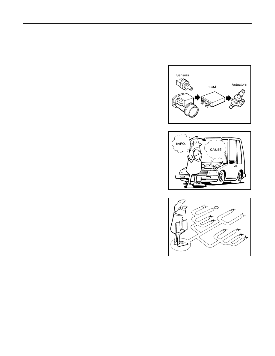
INTRODUCTION

The engine has an ECM to control major systems such as fuel con-
trol, ignition control, idle air control system, etc. The ECM accepts
input signals from sensors and instantly drives actuators. It is essen-
tial that both input and output signals are proper and stable. At the
same time, it is important that there are no malfunctions such as vac-
uum leaks, fouled spark plugs, or other malfunctions with the engine.

It is much more difficult to diagnose an incident that occurs intermit-
tently rather than continuously. Most intermittent incidents are
caused by poor electric connections or improper wiring. In this case,
careful checking of suspected circuits may help prevent the replace-
ment of good parts.

A visual check only may not find the cause of the incidents. A road
test with CONSULT-III (or GST) or a circuit tester connected should
be performed. Follow the Work Flow on "Work Flow".
Before undertaking actual checks, take a few minutes to talk with a
customer who approaches with a driveability complaint. The cus-
tomer can supply good information about such incidents, especially
intermittent ones. Find out what symptoms are present and under
what conditions they occur. A Diagnostic Worksheet like the example
on "Worksheet Sample" should be used.
Start your diagnosis by looking for conventional malfunctions first.
This will help troubleshoot driveability malfunctions on an electroni-
cally controlled engine vehicle.

WORK FLOW

MEF036D

SEF233G

SEF234G

2009 Pathfinder

DIAGNOSIS AND REPAIR WORKFLOW

EC-15

< BASIC INSPECTION >

[VQ40DE]

C

D

E

F

G

H

I

J

K

L

M

A

EC

N

P

O

Overall Sequence

Detailed Flow

1.

GET INFORMATION FOR SYMPTOM

Get the detailed information from the customer about the symptom (the condition and the environment when
the incident/malfunction occurred) using the "DIAGNOSTIC WORKSHEET".

>> GO TO 2.

PBIB3637E

2009 Pathfinder

EC-16

< BASIC INSPECTION >

[VQ40DE]

DIAGNOSIS AND REPAIR WORKFLOW

2.

CHECK DTC*

1

1.

Check DTC*

1

.

2.

Perform the following procedure if DTC*

1

 is displayed.

-

Record DTC*

1

 and freeze frame data*

2

. (Print them out with CONSULT-III or GST.)

-

Erase DTC*

1

. (Refer to 

EC-456, "DTC Index"

.)

-

Study the relationship between the cause detected by DTC*

1

 and the symptom described by the cus-

tomer. (Symptom Matrix Chart is useful. Refer to 

EC-473

.)

3.

Check related service bulletins for information.

Are any symptoms described and any DTCs detected?

Symptom is described, DTC*

1

 is displayed>>GO TO 3.

Symptom is described, DTC*

1

 is not displayed>>GO TO 4.

Symptom is not described, DTC*

1

 is displayed>>GO TO 5.

3.

CONFIRM THE SYMPTOM

Try to confirm the symptom described by the customer (except MIL ON).
DIAGNOSIS WORK SHEET is useful to verify the incident.
Connect CONSULT-III to the vehicle and check diagnosis results.
Verify relation between the symptom and the condition when the symptom is detected.

>> GO TO 5.

4.

CONFIRM THE SYMPTOM

Try to confirm the symptom described by the customer.
DIAGNOSIS WORK SHEET is useful to verify the incident.
Connect CONSULT-III to the vehicle and check diagnosis results.
Verify relation between the symptom and the condition when the symptom is detected.

>> GO TO 6.

5.

PERFORM DTC CONFIRMATION PROCEDURE

Perform DTC Confirmation Procedure for the displayed DTC*

1

, and then make sure that DTC*

1

 is detected

again.
If two or more DTCs*

1

 are detected, refer to 

EC-455, "DTC Inspection Priority Chart"

 and determine trouble

diagnosis order.
NOTE:
• Freeze frame data*

2

 is useful if the DTC*

1

 is not detected.

• Perform Overall Function Check if DTC Confirmation Procedure is not included on Service Manual. This

simplified check procedure is an effective alternative though DTC*

1

 cannot be detected during this check.

If the result of Overall Function Check is NG, it is the same as the detection of DTC*

1

 by DTC Confirmation

Procedure.

Is DTC*

1

 detected?

Yes

>> GO TO 10.

No

>> Check according to 

GI-45, "Work Flow"

.

6.

PERFORM BASIC INSPECTION

Perform 

EC-20, "Basic Inspection"

.

With CONSULT-III>>GO TO 7.
Without CONSULT-III>>GO TO 9.

7.

PERFORM SPEC IN DATA MONITOR MODE

 With CONSULT-III

Make sure that “MAS A/F SE-B1”, “B/FUEL SCHDL”, and “A/F ALPHA-B1”, “A/F ALPHA-B2” are within the SP
value using CONSULT-III “SPEC” in “DATA MONITOR” mode. Refer to 

EC-84, "Description"

.

2009 Pathfinder

DIAGNOSIS AND REPAIR WORKFLOW

EC-17

< BASIC INSPECTION >

[VQ40DE]

C

D

E

F

G

H

I

J

K

L

M

A

EC

N

P

O

Are they within the SP value?

Yes

>> GO TO 9.

No

>> GO TO 8.

8.

DETECT MALFUNCTIONING PART BY TROUBLE DIAGNOSIS - SPECIFICATION VALUE

Detect malfunctioning part according to 

EC-84, "Diagnosis Procedure"

.

Is a malfunctioning part detected?

Yes

>> GO TO 11.

No

>> GO TO 9.

9.

DETECT MALFUNCTIONING SYSTEM BY SYMPTOM MATRIX CHART

Detect malfunctioning system according to 

EC-473, "Symptom Matrix Chart"

 based on the confirmed symptom

in step 4, and determine the trouble diagnosis order based on possible causes and symptoms.

>> GO TO 10.

10.

DETECT MALFUNCTIONING PART BY DIAGNOSTIC PROCEDURE

Inspect according to Diagnostic Procedure of the system.
NOTE:
The Diagnostic Procedure in EC section described based on open circuit inspection. A short circuit inspection
is also required for the circuit check in the Diagnostic Procedure. For details, refer to Circuit Inspection in 

GI-

45, "Work Flow"

.

Is a malfunctioning part detected?

Yes

>> GO TO 11.

No

>> Monitor input data from related sensors or check voltage of related ECM terminals using CON-

SULT-III. Refer to 

EC-421, "CONSULT-III Reference Value in Data Monitor Mode"

EC-424, "ECM

Terminal and Reference Value"

.

11.

REPAIR OR REPLACE THE MALFUNCTIONING PART

1.

Repair or replace the malfunctioning part.

2.

Reconnect parts or connectors disconnected during Diagnostic Procedure again after repair and replace-
ment.

3.

Check DTC. If DTC is displayed, erase it, refer to 

EC-456, "DTC Index"

.

>> GO TO 12.

12.

FINAL CHECK

When DTC was detected in step 2, perform DTC Confirmation Procedure or Overall Function Check again,
and then make sure that the malfunction have been completely repaired.
When symptom was described from the customer, refer to confirmed symptom in step 3 or 4, and make sure
that the symptom is not detected.

OK or NG

NG (DTC*

1

 is detected)>>GO TO 10.

NG (Symptom remains)>>GO TO 6.
OK

>> 1.

Before returning the vehicle to the customer, make sure to always erase unnecessary DTC*

1

in ECM and TCM (Transmission Control Module). (Refer to 

EC-459, "Emission-related Diag-

nostic Information"

 and 

TM-34, "OBD-II Diagnostic Trouble Code (DTC)"

.)

2.

If the completion of SRT is needed, drive vehicle under the specific driving pattern. Refer to

EC-456, "DTC Index"

.

3.

INSPECTION END

*1: Include 1st trip DTC.
*2: Include 1st trip freeze frame data.

DIAGNOSTIC WORKSHEET

Description

2009 Pathfinder

EC-18

< BASIC INSPECTION >

[VQ40DE]

DIAGNOSIS AND REPAIR WORKFLOW

There are many operating conditions that lead to the malfunction of
engine components. A good grasp of such conditions can make trou-
bleshooting faster and more accurate.
In general, each customer feels differently about symptoms. It is
important to fully understand the symptoms or conditions for a cus-
tomer complaint.
Utilize a diagnostic worksheet like the one on the next page in order
to organize all the information for troubleshooting.
Some conditions may cause the MIL to illuminate or blink and DTC
to be detected. Examples:
• Vehicle ran out of fuel, which caused the engine to misfire.
• Fuel filler cap was left off or incorrectly screwed on, allowing fuel to

evaporate into the atmosphere.

SEF907L

2009 Pathfinder

DIAGNOSIS AND REPAIR WORKFLOW

EC-19

< BASIC INSPECTION >

[VQ40DE]

C

D

E

F

G

H

I

J

K

L

M

A

EC

N

P

O

Worksheet Sample

LEC031A

2009 Pathfinder

EC-20

< BASIC INSPECTION >

[VQ40DE]

INSPECTION AND ADJUSTMENT

INSPECTION AND ADJUSTMENT

Basic Inspection

INFOID:0000000004297235

1.

INSPECTION START

1.

Check service records for any recent repairs that may indicate a related malfunction, or a current need for
scheduled maintenance.

2.

Open engine hood and check the following:

-

Harness connectors for improper connections

-

Wiring harness for improper connections, pinches and cut

-

Vacuum hoses for splits, kinks and improper connections

-

Hoses and ducts for leakage

-

Air cleaner clogging

-

Gasket

3.

Check that electrical or mechanical loads are not applied.

-

Headlamp switch is OFF.

-

Air conditioner switch is OFF.

-

Rear window defogger switch is OFF.

-

Steering wheel is in the straight-ahead position, etc.

4.

Start engine and warm it up until engine coolant temperature
indicator points to the middle of gauge.
Ensure engine stays below 1,000 rpm.

5.

Run engine at about 2,000 rpm for about 2 minutes under no
load.

6.

Make sure that no DTC is displayed with CONSULT-III or GST.

OK or NG

OK

>> GO TO 3.

NG

>> GO TO 2.

2.

REPAIR OR REPLACE

Repair or replace components as necessary according to corresponding Diagnostic Procedure.

>> GO TO 3.

3.

CHECK TARGET IDLE SPEED

 With CONSULT-III

1.

Run engine at about 2,000 rpm for about 2 minutes under no load.

SEF983U

SEF976U

SEF977U

2009 Pathfinder

INSPECTION AND ADJUSTMENT

EC-21

< BASIC INSPECTION >

[VQ40DE]

C

D

E

F

G

H

I

J

K

L

M

A

EC

N

P

O

2.

Rev engine (2,000 to 3,000 rpm) two or three times under no
load, then run engine at idle speed for about 1 minute.

3.

Read idle speed in “DATA MONITOR” mode with CONSULT-III.
Refer to 

EC-24, "Idle Speed and Ignition Timing Check"

.

 Without CONSULT-III

1.

Run engine at about 2,000 rpm for about 2 minutes under no load.

2.

Rev engine (2,000 to 3,000 rpm) two or three times under no load, then run engine at idle speed for about
1 minute.

3.

Check idle speed. Refer to 

EC-24, "Idle Speed and Ignition Timing Check"

.

OK or NG

OK

>> GO TO 10.

NG

>> GO TO 4.

4.

PERFORM ACCELERATOR PEDAL RELEASED POSITION LEARNING

1.

Stop engine.

2.

Perform 

EC-25, "Accelerator Pedal Released Position Learning"

.

>> GO TO 5.

5.

PERFORM THROTTLE VALVE CLOSED POSITION LEARNING

Perfor

EC-25, "Throttle Valve Closed Position Learning"

.

>> GO TO 6.

6.

PERFORM IDLE AIR VOLUME LEARNING

Refer to 

EC-25, "Idle Air Volume Learning"

.

Is Idle Air Volume Learning carried out successfully?

Yes or No

Yes

>> GO TO 7.

No

>> 1.

Follow the instruction of Idle Air Volume Learning.

2.

GO TO 4.

7.

CHECK TARGET IDLE SPEED AGAIN

 With CONSULT-III

1.

Start engine and warm it up to normal operating temperature.

2.

Read idle speed in “DATA MONITOR” mode with CONSULT-III.
Refer to 

EC-24, "Idle Speed and Ignition Timing Check"

.

 Without CONSULT-III

1.

Start engine and warm it up to normal operating temperature.

PBIA8513J

625 

±

 50 rpm (in P or N position)

625 

±

 50 rpm (in P or N position)

625 

±

 50 rpm (in P or N position)

2009 Pathfinder


Content      ..     248      249      250      251     ..