Nissan Pathfinder (2009 year). Manual - part 98
DIAGNOSIS AND REPAIR WORKFLOW
BRC-9
< BASIC INSPECTION >
[TYPE 1]
C
D
E
G
H
I
J
K
L
M
A
B
BRC
N
O
P
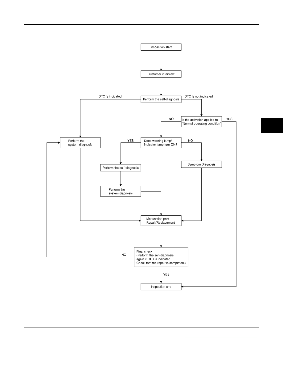
OVERALL SEQUENCE
DETAILED FLOW
1.
COLLECT THE INFORMATION FROM THE CUSTOMER
Get the detailed information from the customer about the symptom (the condition and the environment when
the incident/malfunction occurred) using the diagnosis worksheet. Refer to
BRC-11, "Diagnostic Work Sheet"
.
>> GO TO 2
JSFIA0010GB
2009 Pathfinder