Nissan Pathfinder (2009 year). Manual - part 49


  Index      Manuals     Nissan Pathfinder (2009 year) - Service and Repair Manual


Search            copyright infringement  


Content      ..     47      48      49      50     ..


Nissan Pathfinder (2009 year). Manual - part 49


AV-204

< COMPONENT DIAGNOSIS >

[BOSE AUDIO WITHOUT NAVIGATION]

RGB (R: RED) SIGNAL CIRCUIT

RGB (R: RED) SIGNAL CIRCUIT

Description

INFOID:0000000003939092

Transmit the image displayed with AV control unit with RGB signal to the display unit.

Diagnosis Procedure

INFOID:0000000003939093
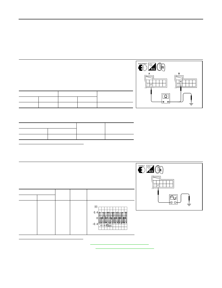
1.

CHECK CONTINUITY RGB (R: RED) SIGNAL CIRCUIT

1.

Turn ignition switch OFF.

2.

Disconnect display unit connector M93 and AV control unit con-
nector M45.

3.

Check continuity between display unit harness connector M93
(A) terminal 17 and AV control unit harness connector M45 (B)
terminal 40.

4.

Check continuity between display unit harness connector M93
(A) terminal 17 and ground.

Are the continuity results as specified?

YES

>> GO TO 2

NO

>> Repair harness or connector.

2.

CHECK RGB (R: RED) SIGNAL

1.

Connect display unit connector M93 and AV control unit connec-
tor M45.

2.

Turn ignition switch ON.

3.

Check signal between display unit harness connector M93 ter-
minal 17 and ground.

Are the voltage readings as specified?

YES

>> Replace display unit. Refer to 

AV-289, "Removal and Installation"

.

NO

>> Replace AV control unit. Refer to 

AV-287, "Removal and Installation"

.

A

B

Continuity

Connector

Terminal

Connector

Terminal

M93

17

M45

40

Yes

A

Continuity

Connector

Terminal

M93

17

Ground

No

ALNIA0382GB

(+)

(-)

Condition

Reference signal

Connector

Terminal

M93

17

Ground

Receive 
audio sig-
nal

ALNIA0383GB

SKIB2238J

2009 Pathfinder

AV

RGB (G: GREEN) SIGNAL CIRCUIT

AV-205

< COMPONENT DIAGNOSIS >

[BOSE AUDIO WITHOUT NAVIGATION]

C

D

E

F

G

H

I

J

K

L

M

B

A

O

P

RGB (G: GREEN) SIGNAL CIRCUIT

Description

INFOID:0000000003939094

Transmit the image displayed with AV control unit with RGB signal to the display unit.

Diagnosis Procedure

INFOID:0000000003939095

1.

CHECK CONTINUITY RGB (G: GREEN) SIGNAL CIRCUIT

1.

Turn ignition switch OFF.

2.

Disconnect display unit connector M93 and AV control unit con-
nector M45.

3.

Check continuity between display unit harness connector M93
(A) terminal 6 and AV control unit harness connector M45 (B)
terminal 39.

4.

Check continuity between display unit harness connector M93
(A) terminal 6 and ground.

Are the continuity results as specified?

YES

>> GO TO 2

NO

>> Repair harness or connector.

2.

CHECK RGB (G: GREEN) SIGNAL

1.

Connect display unit connector M93 and AV control unit connec-
tor M45.

2.

Turn ignition switch ON.

3.

Check signal between display unit harness connector M93 ter-
minal 6 and ground.

Are voltage readings as specified?

YES

>> Replace display unit. Refer to 

AV-289, "Removal and Installation"

.

NO

>> Replace AV control unit. Refer to 

AV-287, "Removal and Installation"

.

A

B

Continuity

Connector

Terminal

Connector

Terminal

M93

6

M45

39

Yes

A

Continuity

Connector

Terminal

M93

6

Ground

No

ALNIA0384GB

(+)

(-)

Condition

Reference signal

Connector

Terminal

M93

6

Ground

Receive 
audio sig-
nal

ALNIA0385GB

SKIB2236J

2009 Pathfinder

AV-206

< COMPONENT DIAGNOSIS >

[BOSE AUDIO WITHOUT NAVIGATION]

RGB (B: BLUE) SIGNAL CIRCUIT

RGB (B: BLUE) SIGNAL CIRCUIT

Description

INFOID:0000000003939096

Transmit the image displayed with AV control unit with RGB signal to the display unit.

Diagnosis Procedure

INFOID:0000000003939097

1.

CHECK CONTINUITY RGB (B: BLUE) SIGNAL CIRCUIT

1.

Turn ignition switch OFF.

2.

Disconnect display unit connector M93 and AV control unit con-
nector M45.

3.

Check continuity between display unit harness connector M93
(A) terminal 18 and AV control unit harness connector M45 (B)
terminal 38.

4.

Check continuity between display unit harness connector M93
(A) terminal 18 and ground.

Are continuity results as specified?

YES

>> GO TO 2

NO

>> Repair harness or connector.

2.

CHECK RGB (B: BLUE) SIGNAL

1.

Connect display unit connector M93 and AV control unit connec-
tor M45.

2.

Turn ignition switch ON.

3.

Check signal between display unit harness connector M93 ter-
minal 18 and ground.

Are voltage readings as specified?

YES

>> Replace display unit. Refer to 

AV-289, "Removal and Installation"

.

NO

>> Replace AV control unit. Refer to 

AV-287, "Removal and Installation"

.

A

B

Continuity

Connector

Terminal

Connector

Terminal

M93

18

M45

38

Yes

A

Continuity

Connector

Terminal

M93

18

Ground

No

ALNIA0386GB

(+)

(-)

Condition

Reference signal

Connector

Terminal

M93

18

Ground

Receive 
audio sig-
nal

ALNIA0387GB

SKIB2237J

2009 Pathfinder

AV

RGB SYNCHRONIZING SIGNAL CIRCUIT

AV-207

< COMPONENT DIAGNOSIS >

[BOSE AUDIO WITHOUT NAVIGATION]

C

D

E

F

G

H

I

J

K

L

M

B

A

O

P

RGB SYNCHRONIZING SIGNAL CIRCUIT

Description

INFOID:0000000003939098

Transmit the RGB synchronizing signal to the display unit so as to synchronize the RGB image displayed with
AV control unit.

Diagnosis Procedure

INFOID:0000000003939099

1.

CHECK CONTINUITY RGB SYNCHRONIZING SIGNAL CIRCUIT

1.

Turn ignition switch OFF.

2.

Disconnect display unit connector M93 and AV control unit con-
nector M45.

3.

Check continuity between display unit harness connector M93
(A) terminal 19 and AV control unit harness connector M45 (B)
terminal 41.

4.

Check continuity between display unit harness connector M93
(A) terminal 19 and ground.

Are continuity results as specified?

YES

>> GO TO 2

NO

>> Repair harness or connector.

2.

CHECK RGB SYNCHRONIZING SIGNAL

1.

Connect display unit connector M93 and AV control unit connec-
tor M45.

2.

Turn ignition switch ON.

3.

Check signal between display unit harness connector M93 ter-
minal 19 and ground.

Are voltage readings as specified?

YES

>> Replace display unit. Refer to 

AV-289, "Removal and Installation"

.

NO

>> Replace AV control unit. Refer to 

AV-287, "Removal and Installation"

.

A

B

Continuity

Connector

Terminal

Connector

Terminal

M93

19

M45

41

Yes

A

Continuity

Connector

Terminal

M93

19

Ground

No

ALNIA0388GB

(+)

(-)

Condition

Reference signal

Connector

Terminal

M93

19

Ground

Receive 
audio sig-
nal

ALNIA0389GB

SKIB3603E

2009 Pathfinder

AV-208

< COMPONENT DIAGNOSIS >

[BOSE AUDIO WITHOUT NAVIGATION]

RGB AREA (YS) SIGNAL CIRCUIT

RGB AREA (YS) SIGNAL CIRCUIT

Description

INFOID:0000000003939100

Transmits the display area of RGB image displayed by AV control unit with RGB area (YS) signal to display
unit.

Diagnosis Procedure

INFOID:0000000003939101

1.

CHECK CONTINUITY RGB AREA (YS) SIGNAL CIRCUIT

1.

Turn ignition switch OFF.

2.

Disconnect display unit connector M93 and AV control unit con-
nector M45.

3.

Check continuity between display unit harness connector M93
(A) terminal 9 and AV control unit harness connector M45 (B)
terminal 43.

4.

Check continuity between display unit harness connector M93
(A) terminal 9 and ground.

Are continuity results as specified?

YES

>> GO TO 2

NO

>> Repair harness or connector.

2.

CHECK RGB SYNCHRONIZING SIGNAL

1.

Connect display unit connector M93 and AV control unit connec-
tor M45.

2.

Turn ignition switch ON.

3.

Check signal between display unit harness connector M93 ter-
minal 9 and ground.

Are voltage readings as specified?

YES

>> Replace display unit. Refer to 

AV-289, "Removal and Installation"

.

NO

>> Replace AV control unit. Refer to 

AV-287, "Removal and Installation"

.

A

B

Continuity

Connector

Terminal

Connector

Terminal

M93

9

M45

43

Yes

A

Continuity

Connector

Terminal

M93

9

Ground

No

ALNIA0390GB

(+)

(-)

Condition

Reference signal

Connector

Terminal

M93

9

Ground

Receive 
audio sig-
nal

ALNIA0391GB

PKIB4948J

2009 Pathfinder

AV

HORIZONTAL SYNCHRONIZING (HP) SIGNAL CIRCUIT

AV-209

< COMPONENT DIAGNOSIS >

[BOSE AUDIO WITHOUT NAVIGATION]

C

D

E

F

G

H

I

J

K

L

M

B

A

O

P

HORIZONTAL SYNCHRONIZING (HP) SIGNAL CIRCUIT

Description

INFOID:0000000003939102

In composite image (AUX image, camera image), transmit the vertical synchronizing (VP) signal and horizon-
tal synchronizing (HP) signal from display unit to AV control unit so as to synchronize the RGB images dis-
played with AV control unit such as the image quality adjusting menu, etc.

Diagnosis Procedure

INFOID:0000000003939103

1.

CHECK CONTINUITY HORIZONTAL SYNCHRONIZING (HP) SIGNAL CIRCUIT

1.

Turn ignition switch OFF.

2.

Disconnect display unit connector M93 and AV control unit con-
nector M45.

3.

Check continuity between display unit harness connector M93
(A) terminal 8 and AV control unit harness connector M45 (B)
terminal 45.

4.

Check continuity between display unit harness connector M93
(A) terminal 8 and ground.

Are continuity results as specified?

YES

>> GO TO 2

NO

>> Repair harness or connector.

2.

CHECK HORIZONTAL SYNCHRONIZING (HP) SIGNAL

1.

Connect display unit connector M93 and AV control unit connec-
tor M45.

2.

Turn ignition switch ON.

3.

Check signal between display unit harness connector M93 ter-
minal 8 and ground.

Are voltage readings as specified?

YES

>> Replace AV control unit. Refer to 

AV-287, "Removal and Installation"

.

NO

>> Replace display unit. Refer to 

AV-289, "Removal and Installation"

.

A

B

Continuity

Connector

Terminal

Connector

Terminal

M93

8

M45

45

Yes

A

Continuity

Connector

Terminal

M93

8

Ground

No

ALNIA0394GB

(+)

(-)

Condition

Reference signal

Connector

Terminal

M93

8

Ground

Receive 
audio sig-
nal

ALNIA0396GB

SKIB3601E

2009 Pathfinder

AV-210

< COMPONENT DIAGNOSIS >

[BOSE AUDIO WITHOUT NAVIGATION]

VERTICAL SYNCHRONIZING (VP) SIGNAL CIRCUIT

VERTICAL SYNCHRONIZING (VP) SIGNAL CIRCUIT

Description

INFOID:0000000003939104

In composite image (AUX image, camera image), transmit the vertical synchronizing (VP) signal and horizon-
tal synchronizing (HP) signal from display unit to AV control unit so as to synchronize the RGB images dis-
played with AV control unit such as the image quality adjusting menu, etc.

Diagnosis Procedure

INFOID:0000000003939105

1.

CHECK CONTINUITY VERTICAL SINCHRONIZING (VP) SIGNAL CIRCUIT

1.

Turn ignition switch OFF.

2.

Disconnect display unit connector M93 and AV control unit con-
nector M45.

3.

Check continuity between display unit harness connector M93
(A) terminal 20 and AV control unit harness connector M45 (B)
terminal 57.

4.

Check continuity between display unit harness connector M93
(A) terminal 20 and ground.

Are continuity results as specified?

YES

>> GO TO 2

NO

>> Repair harness or connector.

2.

CHECK VERTICAL SINCHRONIZING (VP) SIGNAL

1.

Connect display unit connector M93 and AV control unit connec-
tor M45.

2.

Turn ignition switch ON.

3.

Check signal between display unit harness connector M93 ter-
minal 20 and ground.

Are voltage readings as specified?

YES

>> Replace AV control unit. Refer to 

AV-287, "Removal and Installation"

.

NO

>> Replace display unit. Refer to 

AV-289, "Removal and Installation"

.

A

B

Continuity

Connector

Terminal

Connector

Terminal

M93

20

M45

57

Yes

A

Continuity

Connector

Terminal

M93

20

Ground

No

ALNIA0392GB

(+)

(-)

Condition

Reference signal

Connector

Terminal

M93

20

Ground

Receive 
audio sig-
nal

ALNIA0393GB

SKIB3598E

2009 Pathfinder

AV

FRONT DOOR SPEAKER

AV-211

< COMPONENT DIAGNOSIS >

[BOSE AUDIO WITHOUT NAVIGATION]

C

D

E

F

G

H

I

J

K

L

M

B

A

O

P

FRONT DOOR SPEAKER

Description

INFOID:0000000003939106

The AV control unit sends audio signals to the BOSE speaker amp. The BOSE speaker amp. amplifies the
audio signals before sending them to the front door speakers using the audio signal circuits.

Diagnosis Procedure

INFOID:0000000003939107

1.

HARNESS CHECK

1.

Disconnect BOSE speaker amp. connector B75 and suspect
speaker connector.

2.

Check continuity between BOSE speaker amp. harness connec-
tor B75 (A) and suspect speaker harness connector (B).

3.

Check continuity between BOSE speaker amp. harness connec-
tor B75 (A) and ground.

Are continuity test results as specified?

YES

>> GO TO 2

NO

>> • Check connector housings for disconnected or loose terminals.

• Repair harness or connector.

2.

FRONT SPEAKER SIGNAL CHECK

A B

Continuity

Connector

Terminal

Connector

Terminal

B75

13

D12

1

Yes

14

2

15

D112

1

16

2

A

Continuity

Connector

Terminal

B75

13

Ground

No

14

15

16

ALNIA0530GB

2009 Pathfinder


Content      ..     47      48      49      50     ..