Nissan Pathfinder (2008 year). Manual - part 629
WCS-22
< COMPONENT DIAGNOSIS >
KEY SWITCH SIGNAL CIRCUIT (WITH INTELLIGENT KEY)
Is the inspection result normal?
YES
>> GO TO 4
NO
>> Repair harness or connector.
4.
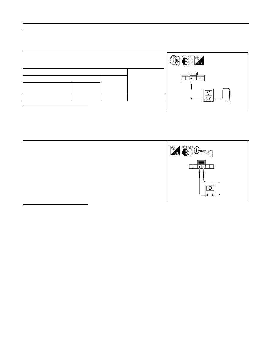
CHECK KEY SWITCH POWER SUPPLY CIRCUIT
Check voltage between key switch and ignition knob switch harness
connector and ground.
Is the inspection result normal?
YES
>> Replace key switch and ignition knob switch.
NO
>> Repair harness or connector.
Component Inspection
INFOID:0000000001712854
1.
CHECK KEY SWITCH
1.
Turn ignition switch OFF.
2.
Disconnect key switch and ignition knob switch connector.
3.
Check continuity between key switch and ignition knob switch
terminals 3 and 4.
Is the inspection result normal?
YES
>> Inspection End.
NO
>> Replace key switch and ignition knob switch.
Terminals
Voltage
(Approx.)
(+)
(
−
)
Key switch and ignition
knob switch connector
Terminal
M66
3
Ground
Battery voltage
AWNIA0240ZZ
3 – 4
When key is inserted
into key cylinder
: Continuity should exist.
When key is removed
from key cylinder
: Continuity should not exist.
AWNIA0241ZZ