Nissan Pathfinder (2008 year). Manual - part 576
 

  Index      Manuals     Nissan Pathfinder (2008 year) - Service and Repair Manual


Search            copyright infringement  


Content      ..     574      575      576      577     ..


Nissan Pathfinder (2008 year). Manual - part 576


PREPARATION

ST-3

< PREPARATION >

C

D

E

F

H

I

J

K

L

M

A

B

ST

N

O

P

PREPARATION

PREPARATION

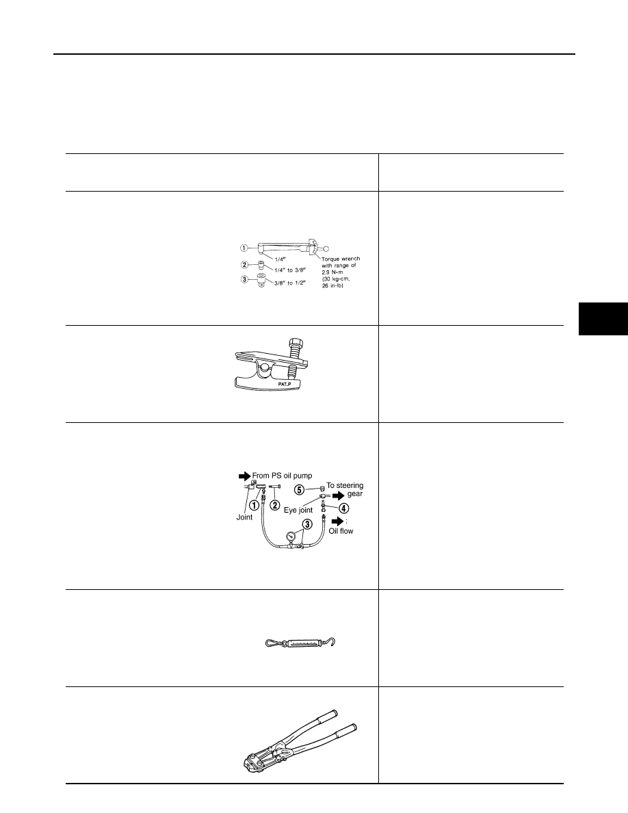
Special Service Tool

INFOID:0000000001297911

The actual shapes of Kent-Moore tools may differ from those of special service tools illustrated here.

Tool number
(Kent-Moore No.)
Tool name

Description

ST3127 S000
(See J-25765-A)
Preload gauge
 1. GG9103000
    (J-25765-A)
    Torque wrench
 2. HT62940000
   (

 —

)

   Socket adapter
 3. HT62900000
   (

— 

)

   Socket adapter

Inspecting of pinion rotating torque and rota-
tional torque for ball joint

HT72520000
(J-25730-A)
Ball joint remover

Removing steering outer socket

1. KV48105300-4 and 5295262U10
(


— 

)

Connector A and O-ring
2. KV48105300-3 and 5295262U00
(


— 

)

Eye-bolt and O-ring
3. KV48103500
(J-26357 and J-26357-10)
Pressure gauge and shut-off valve
4. KV48105300-1 and 5295262U00
(


— 

)

Connector B and O-ring
5. KV48105300-2
(


— 

)

Nut

Measuring oil pump relief pressure

(J-44372)
Spring gauge

Measuring steering wheel turning force

KV40107300
(

)

Crimping boot bands

S-NT541

NT146

SGIA0427E

LST024

ZZA1229D

ST-4

< PREPARATION >

PREPARATION

Commercial Service Tool

INFOID:0000000001297912

KV481J0010  
(J-1859A)
Steering wheel puller

Removing steering wheel

KV481J0020
(J-42578)
Steering wheel puller legs

Removing steering wheel

Tool number
(Kent-Moore No.)
Tool name

Description

LHIA0043E

LHIA0044E

Tool name

Description

Power tool

Removing nuts and bolts

PBIC0190E

HEATED STEERING WHEEL

ST-5

< FUNCTION DIAGNOSIS >

C

D

E

F

H

I

J

K

L

M

A

B

ST

N

O

P

FUNCTION DIAGNOSIS

HEATED STEERING WHEEL

System Diagram

INFOID:0000000001710949

System Description

INFOID:0000000001710950

The heated steering wheel switch controls the heated steering relay. When the switch is turned on, the relay is
energized and the heated steering system will operate. The heated steering system will turn off when the
steering wheel temperature reaches approximately 30

°

 C (86

°

 F). Heated steering system operation can also

be canceled by pressing the heated steering wheel switch again.
NOTE:
The heated steering system will operate ONLY when the steering wheel surface is below approximately 20

°

 C

(68

°

 F). If the weather is warm enough, the heated steering system may not turn on, giving the appearance

that the system does not operate.

Component Parts Location

INFOID:0000000001710951

AWGIA0022GB

1.

Heated steering wheel switch M7

2.

Heated steering relay M2

3.

Combination switch (heated steering) 
M5

4.

Heated steering wheel

ALGIA0025ZZ

ST-6

< FUNCTION DIAGNOSIS >

HEATED STEERING WHEEL

Component Description

INFOID:0000000001710952

Heated steering wheel switch

• Controls the heated steering relay and operates the heated steering system.
• Turns the indicator lamp ON when the system is activated.

Heated steering relay

• Operates the heated steering system with the control signal from the heated steering 

wheel switch.

Heated steering wheel

• Heats the heating element with the power supplied from the heated steering relay.

HEATED STEERING WHEEL

ST-7

< COMPONENT DIAGNOSIS >

C

D

E

F

H

I

J

K

L

M

A

B

ST

N

O

P

COMPONENT DIAGNOSIS

HEATED STEERING WHEEL

Wiring Diagram

INFOID:0000000001710953

ALGWA0006GB

ST-8

< COMPONENT DIAGNOSIS >

HEATED STEERING WHEEL

ALGIA0017GB

NOISE, VIBRATION, AND HARSHNESS (NVH) TROUBLESHOOTING

ST-9

< SYMPTOM DIAGNOSIS >

C

D

E

F

H

I

J

K

L

M

A

B

ST

N

O

P

SYMPTOM DIAGNOSIS

NOISE, VIBRATION, AND HARSHNESS (NVH) TROUBLESHOOTING

NVH Troubleshooting Chart

INFOID:0000000001297913

Use chart below to help you find the cause of the symptom. If necessary, repair or replace these parts.

×

: Applicable

Reference page

ST

-10

ST

-10

ST

-30

ST

-30

ST

-30

ST

-10

ST

-15

ST

-15

EM-13, "

Ch

ec

ki

ng

 Driv

Belt

s

"

 (VQ40D

E

),

EM

-1

5

3

, "

Ch

eck

ing

 Dri

v

Bel

ts

"

 (VK

5

6DE)

ST

-15

ST

-17

ST

-22

ST

-17

ST

-17

ST

-22


DLN

-30

6,

 "

NV

H T

rou

ble

s

ho

oti

n

g

 Cha

rt

"

 (2F

1

31

0),

DLN-314, "

NVH T

ro

u

b

les

ho

ot

ing

 Ch

art

"

 (2S1

33

0),

DLN-323, "

NV

H T

rou

bl

es

ho

oti

n

g

 Cha

rt

"

 (2S1

35

0)

DLN

-33

6,

 "

NVH

 T

ro

u

b

les

ho

ot

in

g

 Ch

art

"

 (R18

0A),

DLN-370, "

NVH T

roub

le

sh

oo

tin

g

 Ch

art

"

 (M

20

5)

F

AX-4, "

NVH T

rou

bl

es

ho

ot

in

g

 Cha

rt

"

FSU-4,

 "

NVH T

ro

u

b

les

ho

ot

in

g Ch

art

"

WT

-33,

 "

NVH T

ro

u

b

les

ho

ot

ing

 Ch

art

"

WT

-33,

 "

NVH T

ro

u

b

les

ho

ot

ing

 Ch

art

"

F

AX-4, "

NVH T

rou

bl

es

ho

ot

in

g

 Cha

rt

"

BR-5, "

NVH T

ro

ubl

es

ho

ot

ing

 Cha

rt

"

Possible cause and suspected parts

F

lui

d l

e

v

e

l

Air i

n

 hy

dra

u

lic

 sy

st

em

Ou

ter so

cket

 ba

ll joi

n

t swi

n

g

ing

 fo

rce

Ou

ter so

cket

 ba

ll joi

n

t rot

a

ti

ng torq

ue

Ou

ter so

ck

et

 ba

ll joi

n

t en

p

la

y

S

tee

rin

g

 f

lui

lea

k

a

g

e

S

te

e

ri

ng

 whe

e

l pl

ay

S

te

e

ri

ng

 ge

ar rac

k

 sl

id

in

g

 f

o

rce

Dri

v

e

 be

lt 

loo

s

ene

s

s

Im

p

rop

er s

te

e

rin

g

 whee

l

Im

p

rop

er i

n

s

tal

la

tio

n

 o

r lo

os

en

es

s

 of

 til

t lo

c

k

 l

e

v

e

r

M

o

u

n

ti

ng

 ru

bb

er d

e

te

rio

rat

ion

S

tee

rin

g

 c

o

lu

m

n

 de

form

at

ion

 o

r da

ma

ge

Im

p

rop

er i

n

s

tal

la

tio

n

 o

r lo

os

en

es

s

 of

 st

ee

ring

 c

o

lu

m

n

S

te

e

ri

ng

 li

nk

ag

e l

o

o

s

e

n

e

s

s

PROPE

LLE

R SHAFT

FR

ONT FINAL 

DRIVE

WH

EE

L

 H

U

B

SUS

PENSION

TI

RE

S

ROAD W

H

EEL

DRIV

E

 SHAFT

BRA

KES

Symptom

Noise

× × × × × × × ×

×

×

×

× × × × × ×

Shake

× × ×

×

× × × × × ×

Vibration

× × × × ×

×

× × ×

×

Shimmy

× × ×

×

× × × ×

×

Shudder

×

×

× × × ×

×

ST-10

< ON-VEHICLE MAINTENANCE >

POWER STEERING FLUID

ON-VEHICLE MAINTENANCE

POWER STEERING FLUID

Checking Fluid Level

INFOID:0000000001297914

Check fluid level, referring to the scale on the reservoir tank.
Use HOT range for fluid temperatures of 50

°

 – 80

°

C (122

°

 – 176

°

F).

Use COLD range for fluid temperatures of 0

°

 – 30

°

C (32

°

 – 86

°

F).

CAUTION:

• Do not overfill.
• Do not reuse any power steering fluid.
• Recommended fluid is Genuine NISSAN PSF or equivalent.

Refer to 

MA-10, "Fluids and Lubricants"

.

Checking Fluid Leakage

INFOID:0000000001297915

Check the hydraulic piping lines for improper attachment, leaks,
cracks, damage, loose connections, chafing and deterioration.

1.

Run the engine until the fluid temperature reaches 50

°

 – 80

°

C

(122

°

 – 176

°

F) in the reservoir tank. Keep engine speed idle.

CAUTION:

Do not allow steering fluid reservoir tank to go below the
MIN level line. Check tank frequently and add fluid as
needed.

2.

Turn the steering wheel to the right and left several times.

3.

Hold the steering wheel at each “locked” position for five sec-
onds to check for fluid leakage.

CAUTION:

Do not hold steering wheel in the locked position for more than 10 seconds. (There is the possibil-
ity that the oil pump may be damaged.)

4.

If fluid leakage at a connection is noticed, loosen the connection and then retighten. Do not over-tighten
connector as this can damage O-ring, washer and connector. Refer to 

ST-14

 and 

ST-26

.

5.

If fluid leakage from the oil pump is noticed, check the oil pump. Refer to 

ST-14

.

6.

Check steering gear boots for accumulation of fluid, indicating a leak from the steering gear.

CAUTION:

Do not reuse copper washers.

Air Bleeding Hydraulic System

INFOID:0000000001297916

Incomplete air bleeding causes the following:

• Air bubbles in reservoir tank
• Clicking noise in oil pump
• Excessive buzzing in oil pump
When this happens bleed the air again.
NOTE:
When the vehicle is stationary or while the steering wheel is being turned slowly, some noise may be heard
from the oil pump or gear. This noise is normal and does not affect any system.
1.

Check for fluid leakage. Refer to 

ST-10, "Checking Fluid Leakage"

.

2.

Start the engine and turn the steering wheel fully to the right and left several times.

CAUTION:

Do not allow steering fluid reservoir tank to go below the MIN level line. Check tank frequently and
add fluid as needed.

3.

Run the engine at idle speed. Hold the steering wheel at each "locked" position for three seconds.

CAUTION:

LGIA0021E

SGIA0506E


Content      ..     574      575      576      577     ..