Nissan Pathfinder (2008 year). Manual - part 535


  Index      Manuals     Nissan Pathfinder (2008 year) - Service and Repair Manual


Search            copyright infringement  


Content      ..     533      534      535      536     ..


Nissan Pathfinder (2008 year). Manual - part 535


RF-38

< SYMPTOM DIAGNOSIS >

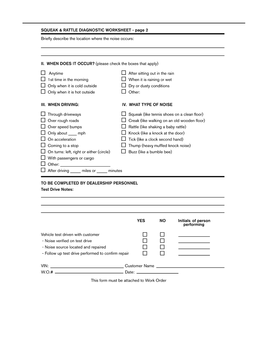
SQUEAK AND RATTLE TROUBLE DIAGNOSES

LAIA0071E

PRECAUTIONS

RF-39

< PRECAUTION >

C

D

E

F

G

H

I

J

L

M

A

B

RF

N

O

P

PRECAUTION

PRECAUTIONS

Precaution for Supplemental Restraint System (SRS) "AIR BAG" and "SEAT BELT 
PRE-TENSIONER"

INFOID:0000000001694259

The Supplemental Restraint System such as “AIR BAG” and “SEAT BELT PRE-TENSIONER”, used along
with a front seat belt, helps to reduce the risk or severity of injury to the driver and front passenger for certain
types of collision. This system includes seat belt switch inputs and dual stage front air bag modules. The SRS
system uses the seat belt switches to determine the front air bag deployment, and may only deploy one front
air bag, depending on the severity of a collision and whether the front occupants are belted or unbelted.
Information necessary to service the system safely is included in the SR and SB section of this Service Man-
ual.

WARNING:

• To avoid rendering the SRS inoperative, which could increase the risk of personal injury or death in

the event of a collision which would result in air bag inflation, all maintenance must be performed by
an authorized NISSAN/INFINITI dealer.

• Improper maintenance, including incorrect removal and installation of the SRS, can lead to personal

injury caused by unintentional activation of the system. For removal of Spiral Cable and Air Bag
Module, see the SR section.

• Do not use electrical test equipment on any circuit related to the SRS unless instructed to in this

Service Manual. SRS wiring harnesses can be identified by yellow and/or orange harnesses or har-
ness connectors.

Precaution

INFOID:0000000001694260

• Disconnect both battery cables in advance.
• Never tamper with or force air bag lid open, as this may adversely affect air bag performance.
• Be careful not to scratch pad and other parts.
• When removing or disassembling any part, be careful not to damage or deform it. Protect parts which may

get in the way with cloth.

• When removing parts with a screwdriver or other tool, protect parts by wrapping them with vinyl or tape. 
• Keep removed parts protected with cloth.
• If a clip is deformed or damaged, replace it.
• If an unreusable part is removed, replace it with a new one.
• Tighten bolts and nuts firmly to the specified torque.
• After re-assembly has been completed, make sure each part functions correctly.
• Remove stains in the following way.
Water-soluble stains:
Dip a soft cloth in warm water, and then squeeze it tightly. After wiping the stain, wipe with a soft dry cloth.
Oil stain:
Dissolve a synthetic detergent in warm water (density of 2 to 3% or less), dip the cloth, then clean off the stain
with the cloth. Next, dip the cloth in fresh water and squeeze it tightly. Then clean off the detergent completely.
Then wipe the area with a soft dry cloth.
• Do not use any organic solvent, such as thinner or benzine.

RF-40

< PREPARATION >

PREPARATION

PREPARATION

PREPARATION

Special Service Tool

INFOID:0000000001694261

The actual shapes of Kent-Moore tools may differ from those of special service tools illustrated here.

Commercial Service Tool

INFOID:0000000001694262

Tool number
(Kent-Moore No.)
Tool name

Description

(J-39570)
Chassis ear

Locating the noise

(J-43980)
NISSAN Squeak and
Rattle Kit

Repairing the cause of noise

SIIA0993E

SIIA0994E

(Kent-Moore No.)
Tool name

Description

(J-39565)
Engine ear

Locating the noise

SIIA0995E

SUNROOF SYSTEM

RF-41

< ON-VEHICLE REPAIR >

C

D

E

F

G

H

I

J

L

M

A

B

RF

N

O

P

ON-VEHICLE REPAIR

SUNROOF SYSTEM

Adjustment

INFOID:0000000001694266

Inspect then measure the gap and height difference between the glass lid assembly and roof panel; compare
to specifications. Determine which procedure to follow based on results of measurements. 

GAP ADJUSTMENT 

If a gap or minor height difference between glass lid assembly and roof panel is found, adjust in the following
manner:
1.

Open sunshade assembly and tilt glass lid assembly up.

2.

Loosen glass lid assembly screws (2 each on left and right sides), then tilt glass lid assembly down.

3.

Manually adjust glass lid assembly from outside of vehicle so it is within specification "A-A" as shown.

4.

After adjustment, tilt glass lid assembly up and tighten screws.

5.

Tilt glass lid assembly up and down several times to check that it moves and seals properly.

HEIGHT DIFFERENCE ADJUSTMENT

If an excessive height difference between glass lid assembly and roof panel is found, adjust in the following
manner:

1.

Remove headlining. Refer to 

INT-16, "Removal and Installation"

.

2.

Loosen sunroof frame assembly nuts and sunroof bracket bolts.

3.

Add shims until gap is within specification "A-A" as shown.
NOTE:
Temporarily snug nuts and bolts to prevent movement between each adjustment.

4.

Tilt glass lid assembly up and down several times to check that it moves and seals properly.

5.

Tighten sunroof frame assembly nuts and sunroof bracket bolts. 
NOTE:

A.

0.8 

±

 1.5mm (0.03 

±

 0.06 in.)

B.

4.0 

±

 0.7mm (0.16 

±

 0.03 in)

WIIA1071E

RF-42

< ON-VEHICLE REPAIR >

SUNROOF SYSTEM

First tighten left front then right rear sunroof frame assembly nuts to prevent uneven torque while tighten-
ing remaining sunroof bracket bolts.

6.

Install headlining. Refer to 

INT-16, "Removal and Installation"

.

Removal and Installation

INFOID:0000000001694267

WIIA0423E

SUNROOF SYSTEM

RF-43

< ON-VEHICLE REPAIR >

C

D

E

F

G

H

I

J

L

M

A

B

RF

N

O

P

• After any adjustment, check sunroof operation and glass lid alignment.
• Handle glass lid with care so not to cause damage.
• For easier installation, mark each point before removal.

CAUTION:

• Always work with a helper.
• Before removal, fully close the glass lid assembly. Then, after removal, do not move the motor

assembly.

• After installing the sunroof and glass lid, check gap adjustment to ensure there is no malfunction.

SUNROOF UNIT

Removal

CAUTION:

• Always work with a helper.
• When taking sunroof unit out, use shop cloths to protect the seats and trim from damage.
• After installing the sunroof unit and glass lid, be sure to check gap adjustment to ensure there is no

malfunction.

1.

Remove headlining. Refer to 

INT-16, "Removal and Installation"

2.

Remove the sunroof glass lid.

3.

Disconnect sunroof motor and remove the overhead console bracket.

4.

Disconnect the drain hoses.

5.

Remove front sunroof frame assembly nuts.

6.

Remove the rear sunroof bracket bolts. 

7.

Remove the side bolts and the sunroof unit.

Installation

1.

Position the sunroof frame assembly and install the side bolts.

2.

Install the rear sunroof bracket bolts.

3.

Install front sunroof frame assembly nuts.

4.

Connect the drain hoses.

5.

Install the overhead console bracket and connect the sunroof motor.

6.

Install the sunroof glass lid.

7.

Install headlining. Refer to 

INT-16, "Removal and Installation"

.

GLASS LID

Removal

1.

Open sunshade.

2.

Ensure glass lid is closed.

3.

Remove the screws securing glass lid to the sunroof frame assembly.

4.

Remove the glass lid assembly.

Installation

1.

Position glass lid to sunroof assembly.

1.

Glass lid assembly

2.

Wind deflector

3.

Rear drain hoses

4.

Shade stoppers

5.

Sunroof bracket 

6.

Sunroof frame assembly

7.

Front drain hoses

8.

Sunroof motor assembly

9.

Sunshade assembly

RF-44

< ON-VEHICLE REPAIR >

SUNROOF SYSTEM

2.

Install the glass lid assembly screws. (First tighten left front bolt,
then tighten right rear bolt on glass lid to prevent lid from moving
while tightening other bolts.) 

3.

Adjust the sunroof glass. Refer to 

RF-41, "Adjustment"

.

WIND DEFLECTOR

Removal

1.

Open the sunroof.

2.

Remove screws from the left, center, and right side wind deflec-
tor holders.

3.

Remove the wind deflector from the sunroof frame assembly.

Installation

Installation is in the reverse order of removal.

SUNSHADE

Removal

1.

Remove the sunroof frame assembly. Refer to 

RF-42, "Removal and Installation"

.

2.

Remove the sunshade stoppers (2 points) from the rear end of
the sunroof frame assembly.

3.

Remove the sunshade assembly from the rear end of the sun-
roof frame assembly.

Installation

Installation is in the reverse order of removal.

SUNROOF MOTOR

Removal

CAUTION:

• When removing the sunroof motor, be sure that the sunroof is in the fully closed position.
• Never run the removed motor as a single unit.

1.

Position the sunroof assembly in the fully closed position.

2.

Remove the front roof console assembly. Refer to 

INT-16, "Removal and Installation"

.

WIIA0252E

WIIA0424E

LIIA1672E

SUNROOF SYSTEM

RF-45

< ON-VEHICLE REPAIR >

C

D

E

F

G

H

I

J

L

M

A

B

RF

N

O

P

3.

Disconnect the harness connector from the sunroof motor
assembly.

4.

Remove the mounting screws and the sunroof motor assembly.

Installation

CAUTION:

Before installing the sunroof motor assembly, be sure to place the link and wire assembly in the sym-
metrical and fully closed position.
1.

Move the sunroof motor assembly laterally little by little so that
the gear is completely engaged into the wire on the sunroof unit
and the mounting surface becomes parallel. Then secure the
motor with bolts.

2.

Connect the harness connector to the sunroof motor assembly.

3.

Install the front roof console assembly. Refer to 

INT-16, "Removal and Installation"

.

4.

Reset the sunroof motor memory. Refer to 

RF-5, "ADDITIONAL SERVICE WHEN REPLACING CON-

TROL UNIT : Special Repair Requirement"

.

DRAIN HOSES

Removal

LIIA1673E

LIIA1674E

1.

Drain hoses

WIIA1072E


Content      ..     533      534      535      536     ..