Nissan Pathfinder (2008 year). Manual - part 440
HAC-64
< COMPONENT DIAGNOSIS >
[AUTOMATIC AIR CONDITIONER]
REAR AIR CONTROL SYSTEM
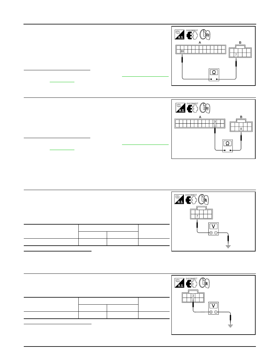
1.
Turn ignition switch OFF.
2.
Disconnect A/C auto amp. connector.
3.
Check continuity between A/C auto amp. harness connector
M50 (A) terminal 37 and rear air control (front) harness connec-
tor R2 (B) terminal 7.
Is the inspection result normal?
YES
>> Replace A/C auto amp. Refer to
NO
>> Repair harness or connector.
8.
CHECK REAR AIR CONTROL (FRONT) REFERENCE GROUND CIRCUIT FOR OPEN
1.
Disconnect A/C auto amp. connector.
2.
Check continuity between A/C auto amp. harness connector
M49 (A) terminal 3 and rear air control (front) harness connector
R2 (B) terminal 8.
Is the inspection result normal?
YES
>> Replace A/C auto amp. Refer to
NO
>> Repair harness or connector.
Rear Air Control (Rear) Diagnosis Procedure
INFOID:0000000001366726
DIAGNOSTIC PROCEDURE FOR REAR AIR CONTROL (REAR)
1.
CHECK REAR AIR CONTROL (REAR) AUX TEMPERATURE POT VOLTAGE
1.
Turn ignition switch OFF.
2.
Disconnect rear air control (rear).
3.
Turn ignition switch ON.
4.
Check voltage between rear air control (rear) harness connector
M208 terminal 7 and ground.
Is the inspection result normal?
YES
>> GO TO 2.
NO
>> GO TO 5.
2.
CHECK REAR AIR CONTROL (REAR) REFERENCE VOLTAGE
Check voltage between rear air control (rear) harness connector
M208 terminal 3 and ground.
Is the inspection result normal?
YES
>> GO TO 3.
NO
>> GO TO 6
3.
CHECK REAR AIR CONTROL (REAR) REFERENCE RETURN GROUND
Continuity should exist.
AWIIA0235ZZ
Continuity should exist.
AWIIA0261ZZ
Connector
Terminals
Voltage (Ap-
prox.)
(+)
(-)
Rear air control (rear): M208
7
Ground
4.5V
AWIIA0258ZZ
Connector
Terminals
Voltage (Ap-
prox.)
(+)
(-)
Rear air control (rear): M208
3
Ground
4.5V
AWIIA0257ZZ