Nissan Pathfinder (2008 year). Manual - part 436


  Index      Manuals     Nissan Pathfinder (2008 year) - Service and Repair Manual


Search            copyright infringement  


Content      ..     434      435      436      437     ..


Nissan Pathfinder (2008 year). Manual - part 436


HAC-32

< COMPONENT DIAGNOSIS >

[AUTOMATIC AIR CONDITIONER]

AIR MIX DOOR MOTOR

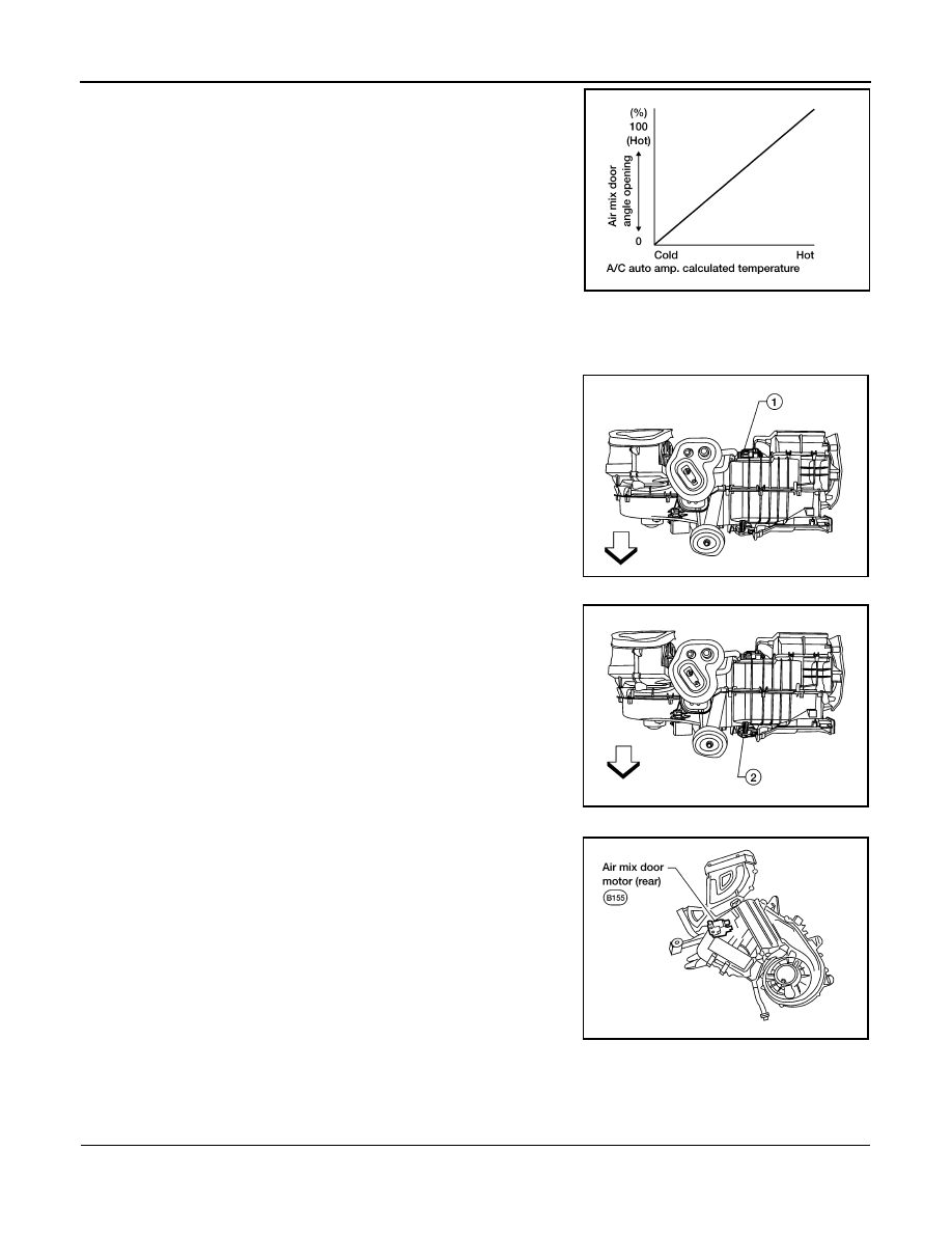
Air Mix Door Control Specification

COMPONENT DESCRIPTION

Air Mix Door Motors (front)

The driver (2) and passenger (1) air mix door motors are attached to
the front heater & cooling unit assembly. These motors rotate so that
the air mix door is opened or closed to a position set by the A/C auto
amp. Motor rotation is then conveyed through a shaft and the air mix
door position is then fed back to the A/C auto amp. by the PBR built
into the air mix door motors.

Air Mix Door Motor (rear)

The air mix door motor (rear) (1) is attached to the rear heater &
cooling unit assembly. These motors rotate so that the air mix door is
opened or closed to a position set by the front (or rear) air control.
Motor rotation is then conveyed through a shaft and the air mix door
position is then fed back to the A/C auto amp. by the PBR built into
the air mix door motors.

Air Mix Door Motor Component Function Check

INFOID:0000000001366705

INSPECTION FLOW

1.

CONFIRM SYMPTOM BY PERFORMING OPERATIONAL CHECK - TEMPERATURE INCREASE

1.

Turn the temperature control dial (driver) clockwise until 32

°

C (90

°

F) is displayed.

2.

Check for hot air at discharge air outlets.

AWIIA0107GB

WJIA1978E

WJIA1979E

WJIA1979E

WJIA1245E

AIR MIX DOOR MOTOR

HAC-33

< COMPONENT DIAGNOSIS >

[AUTOMATIC AIR CONDITIONER]

C

D

E

F

G

H

J

K

L

M

A

B

HAC

N

O

P

>> GO TO 2.

2.

CONFIRM SYMPTOM BY PERFORMING OPERATIONAL CHECK - TEMPERATURE DECREASE

1.

Turn the temperature control dial (driver) counterclockwise until 18

°

C (60

°

F) is displayed.

2.

Check for cold air at discharge air outlets.

Can a symptom be duplicated?

YES

>> GO TO 4.

NO

>> GO TO 3.

3.

PERFORM COMPLETE OPERATIONAL CHECK

Perform a complete operational check and check for any symptoms. Refer to 

HAC-123, "Operational Check"

.

Can a symptom be duplicated?

YES

>> Refer to 

HAC-122, "How to Perform Trouble Diagnosis For Quick And Accurate Repair"

.

NO

>> System OK.

4.

CHECK FOR SERVICE BULLETINS

Check for any service bulletins.

>> GO TO 5.

5.

CHECK AIR MIX DOOR OPERATION

Check and verify air mix door mechanism for smooth operation from 18

°

C (60

°

F) to 32

°

C (90

°

F) in each

mode.
Is the inspection result normal?

YES

>> GO TO 6.

NO

>> Repair as necessary.

6.

PERFORM SELF-DIAGNOSIS

Perform self-diagnosis to check for any codes. Refer to 

HAC-23, "A/C Auto Amp. Self-Diagnosis"

.

Are any self-diagnosis codes present?

YES

>> Refer to 

HAC-24, "A/C System Self-Diagnosis Code Chart"

.

NO

>> GO TO 7.

7.

CHECK THE AIR MIX DOOR MOTOR PBR CIRCUIT 

Perform diagnostic procedure for the air mix door motors. Refer to 

HAC-140, "Air Mix Door Motor Component

Function Check"

.

Is the inspection result normal?

YES

>> GO TO 8.

NO

>> Repair PBR circuit or replace air mix door motor. Refer to 

VTL-29, "Removal and Installation"

.

8.

RECHECK FOR CODES 

Perform self-diagnosis. Refer to 

HAC-23, "A/C and AV Switch Assembly Self-Diagnosis"

.

Are any self-diagnostic codes present?

YES

>> Refer to 

HAC-24, "A/C System Self-Diagnosis Code Chart"

.

NO

>> GO TO 9.

9.

RECHECK FOR ANY SYMPTOMS 

Perform a complete operational check for any symptoms. Refer to 

HAC-123, "Operational Check"

.

Does another symptom exist?

YES

>> Refer to 

HAC-122, "How to Perform Trouble Diagnosis For Quick And Accurate Repair"

NO

>> Replace A/C auto amp. Refer to 

VTL-8, "Removal and Installation"

.

Air Mix Door Motor (Driver) Diagnosis Procedure

INFOID:0000000001366706

SYMPTOM:

• Discharge air temperature does not change.

HAC-34

< COMPONENT DIAGNOSIS >

[AUTOMATIC AIR CONDITIONER]

AIR MIX DOOR MOTOR

• Air mix door motor does not operate.

DIAGNOSTIC PROCEDURE FOR AIR MIX DOOR MOTOR (DRIVER)

1.

CHECK A/C AUTO AMP. FOR POWER AND GROUND 

1.

Turn ignition switch ON.

2.

Rotate temperature control dial (driver) to 32

°

C (90

°

F).

3.

Check voltage between A/C auto amp. harness connector M49
terminal 17 and terminal 18 while rotating temperature control
dial (driver) to 18

°

C (60

°

F).

Is the inspection result normal?

YES

>> GO TO 4.

NO

>> GO TO 3.

2.

CHECK AIR MIX DOOR MOTOR (DRIVER) CIRCUITS FOR SHORT TO GROUND 

1.

Turn ignition switch OFF.

2.

Disconnect the A/C auto amp. harness connector.

3.

Check continuity between A/C auto amp. harness connector
M49 terminal 17, 18 and ground.

Is the inspection result normal?

YES

>> Replace A/C auto amp. Refer to 

VTL-8, "Removal and

Installation"

.

NO

>> Repair or replace harness as necessary.

3.

CHECK A/C AUTO AMP. FOR POWER AND GROUND 

1.

Turn ignition switch ON.

2.

Rotate temperature control dial (driver) to 32

°

C (90

°

F).

3.

Check voltage between A/C auto amp. harness connector M49
terminal 17 and terminal 18 while rotating temperature control
dial (driver) to 18

°

C (60

°

F).

Is the inspection result normal?

YES

>> GO TO 5.

NO

>> Replace A/C auto amp. Refer to 

VTL-8, "Removal and Installation"

.

4.

CHECK AIR MIX DOOR MOTOR (DRIVER) CIRCUITS FOR OPEN

Connector

Terminals

Condition 

Voltage 

(Approx.)

(+) (-)

A/C auto amp.: 

M49

17 18

Rotate temp 

control dial

Battery 
voltage

AWIIA0112ZZ

17 - Ground

: Continuity should not exist.

18 - Ground

: Continuity should not exist.

AWIIA0114ZZ

Connector

Terminals

Condition 

Voltage 

(Approx.)

(+) (-)

A/C auto amp.: 

M49

18 17

Rotate temp 

control dial

Battery 
voltage

AWIIA0115ZZ

AIR MIX DOOR MOTOR

HAC-35

< COMPONENT DIAGNOSIS >

[AUTOMATIC AIR CONDITIONER]

C

D

E

F

G

H

J

K

L

M

A

B

HAC

N

O

P

1.

Turn ignition switch OFF.

2.

Disconnect the A/C auto amp. harness connector.

3.

Check continuity between A/C auto amp. harness connector
M49 terminal 17 and terminal 18.

Is the inspection result normal?

YES

>> GO TO 7.

NO

>> GO TO 6.

5.

CHECK AIR MIX DOOR MOTOR (DRIVER) CIRCUITS FOR OPEN 

1.

Disconnect the air mix door motor (driver) harness connector.

2.

Check continuity between A/C auto amp. harness connector
M49 (A) terminal 17, 18 and the air mix door motor (driver) har-
ness connector M147 (B) terminal 5, 6.

Is the inspection result normal?

YES

>> Replace air mix door motor (driver). Refer to 

VTL-29,

"Removal and Installation"

.

NO

>> Repair or replace harness as necessary.

6.

CHECK A/C AUTO AMP. FOR PBR POWER AND GROUND

1.

Reconnect A/C auto amp. harness connector.

2.

Turn ignition switch ON.

3.

Check voltage between A/C auto amp. harness connector M50
(A) terminal 28 and M49 (B) terminal 3.

Is the inspection result normal?

YES

>> GO TO 9.

NO

>> GO TO 8.

7.

CHECK PBR REFERENCE VOLTAGE CIRCUIT FOR SHORT TO GROUND

1.

Turn ignition switch OFF.

2.

Disconnect the A/C auto amp. harness connector.

3.

Check continuity between A/C auto amp. harness connector
M50 terminal 28 and ground.

Is the inspection result normal?

YES

>> Replace A/C auto amp. Refer to 

VTL-8, "Removal and

Installation"

.

NO

>> Repair or replace harness as necessary.

8.

CHECK PBR REFERENCE VOLTAGE AND GROUND CIRCUITS

Continuity should exist.

AWIIA0116ZZ

17 - 6

: Continuity should exist.

18 - 5

: Continuity should exist.

AWIIA0228ZZ

Connector

Terminals

Voltage (Ap-

prox.)

(+)

(-)

A/C auto amp.: M50, M49

28 

3

5V

AWIIA0118ZZ

Continuity should not exist.

AWIIA0119ZZ

HAC-36

< COMPONENT DIAGNOSIS >

[AUTOMATIC AIR CONDITIONER]

AIR MIX DOOR MOTOR

1.

Turn ignition switch OFF.

2.

Disconnect the A/C auto amp. harness connector.

3.

Check continuity between A/C auto amp. harness connector
M50 (A) terminal 28 and M49 (B) terminal 3.

Is the inspection result normal?

YES

>> GO TO 11.

NO

>> GO TO 10.

9.

CHECK PBR REFERENCE VOLTAGE CIRCUIT FOR OPEN

1.

Disconnect the air mix door motor (driver) harness connector.

2.

Check continuity between air mix door motor (driver) harness
connector M147 (B) terminal 3, 1 and A/C auto amp. harness
connector M49 (C) terminal 3 and M50 (A) terminal 28.

Is the inspection result normal?

YES

>> Replace air mix door motor (driver). Refer to 

VTL-29,

"Removal and Installation"

.

NO

>> Repair or replace harness as necessary.

10.

CHECK PBR FEEDBACK VOLTAGE

1.

Reconnect the A/C auto amp. harness connector.

2.

Turn ignition switch ON.

3.

Check voltage between A/C auto amp. harness connector M49
terminal 6 and ground while rotating temperature control dial
from 32

°

C (90

°

F) to 18

°

C (60

°

F).

Is the inspection result normal?

YES

>> GO TO 13.

NO

>> GO TO 12.

11.

CHECK PBR FEEDBACK SIGNAL CIRCUIT FOR SHORT TO GROUND

1.

Turn ignition switch OFF.

2.

Disconnect A/C auto amp. harness connector.

3.

Check continuity between A/C auto amp. harness connector
M49 terminal 6 and ground.

Is the inspection result normal?

YES

>> Replace A/C auto amp. Refer to 

VTL-8, "Removal and

Installation"

.

NO

>> Repair or replace harness as necessary.

12.

CHECK PBR FEEDBACK CIRCUIT FOR OPEN

Continuity should exist.

AWIIA0120ZZ

28 - 1

: Continuity should exist.

3 - 3

: Continuity should exist.

AWIIA0229ZZ

 Voltage

: Approx. .5V - 4.5V

AWIIA0122ZZ

Continuity should not exist.

AWIIA0123ZZ

AIR MIX DOOR MOTOR

HAC-37

< COMPONENT DIAGNOSIS >

[AUTOMATIC AIR CONDITIONER]

C

D

E

F

G

H

J

K

L

M

A

B

HAC

N

O

P

1.

Turn ignition switch OFF.

2.

Disconnect the air mix door motor (driver) harness connector
and A/C auto amp. harness connector.

3.

Check continuity between air mix door motor (driver) harness
connector M147 (B) terminal 2 and A/C auto amp. harness con-
nector M49 (A) terminal 6.

Is the inspection result normal?

YES

>> Replace air mix door motor (driver). Refer to 

VTL-29,

"Removal and Installation"

.

NO

>> Repair or replace harness as necessary.

Air Mix Door Motor (Passenger) Diagnosis Procedure

INFOID:0000000001366707

SYMPTOM:

• Discharge air temperature does not change.
• Air mix door motor does not operate.

DIAGNOSTIC PROCEDURE FOR AIR MIX DOOR MOTOR (PASSENGER)

1.

CHECK A/C AUTO AMP. FOR POWER AND GROUND 

1.

Turn ignition switch ON.

2.

Rotate temperature control dial (passenger) to 32

°

C (90

°

F).

3.

Check voltage between A/C auto amp. harness connector M49
terminal 14 and terminal 2 while rotating temperature control dial
(passenger) to 18

°

 C (60

°

 F).

Is the inspection result normal?

OK

>> GO TO 4.

NG

>> GO TO 3.

2.

CHECK AIR MIX DOOR MOTOR (PASSENGER) CIRCUITS FOR SHORT TO GROUND 

1.

Turn ignition switch OFF.

2.

Disconnect the A/C auto amp. harness connector.

3.

Check continuity between A/C auto amp. harness connector
M49 terminal 14, 2 and ground.

Is the inspection result normal?

YES 

>> Replace A/C auto amp. Refer to 

VTL-8, "Removal and

Installation"

.

NO

>> Repair or replace harness as necessary.

3.

CHECK A/C AUTO AMP. FOR POWER AND GROUND 

Continuity should exist.

AWIIA0230ZZ

Connector

Terminals

Condition 

Voltage 

(Approx.)

(+) (-)

A/C auto amp.: 

M49

2 14

Rotate temp 

control dial

Battery 
voltage

AWIIA0125ZZ

14 - Ground

: Continuity should not exist.

2 - Ground

: Continuity should not exist.

AWIIA0126ZZ

HAC-38

< COMPONENT DIAGNOSIS >

[AUTOMATIC AIR CONDITIONER]

AIR MIX DOOR MOTOR

1.

Turn ignition switch ON.

2.

Rotate temperature control dial (passenger) to 16

°

C (60

°

F).

3.

Check voltage between A/C auto amp. harness connector M49
terminal 14 and terminal 2 while rotating temperature control dial
(passenger) to 32

°

C (90

°

F).

Is the inspection result normal?

YES

>> GO TO 5.

NO

>> Replace A/C auto amp. Refer to 

VTL-8, "Removal and Installation"

.

4.

CHECK AIR MIX DOOR MOTOR (PASSENGER) CIRCUITS FOR OPEN

1.

Turn ignition switch OFF.

2.

Disconnect the A/C auto amp. harness connector.

3.

Check continuity between A/C auto amp. harness connector
M50 terminal 14 and terminal 2.

Is the inspection result normal?

YES

>> GO TO 7.

NO

>> GO TO 6.

5.

CHECK AIR MIX DOOR MOTOR (PASSENGER) CIRCUITS FOR OPEN 

1.

Disconnect the air mix door motor (passenger) harness connec-
tor.

2.

Check continuity between A/C auto amp. harness connector
M49 terminal 14, 2 and the air mix door motor (passenger) har-
ness connector M143 terminal 5, 6.

Is the inspection result normal?

YES

>> Replace air mix door motor (passenger). Refer to 

VTL-

29, "Removal and Installation"

.

NO

>> Repair or replace harness as necessary.

6.

CHECK A/C AUTO AMP. FOR PBR POWER AND GROUND

1.

Reconnect A/C auto amp. harness connector.

2.

Turn ignition switch ON.

3.

Check voltage between A/C auto amp. harness connector M50
(A) terminal 28 and M49 (B) terminal 3.

Is the inspection result normal?

YES

>> GO TO 9.

NO

>> GO TO 8.

7.

CHECK PBR REFERENCE VOLTAGE CIRCUIT FOR SHORT TO GROUND

Connector

Terminals

Condition 

Voltage 

(Approx.)

(+) (-)

A/C auto amp.: 

M49

14 2

Rotate temp 

control dial

Battery 
voltage

AWIIA0127ZZ

Continuity should exist.

AWIIA0128ZZ

14 - 6

: Continuity should exist.

2 - 5

: Continuity should exist.

AWIIA0231ZZ

Connector

Terminals

Voltage (Ap-

prox.)

(+)

(-)

A/C auto amp.: M49

28 

3

5V

AWIIA0099ZZ

AIR MIX DOOR MOTOR

HAC-39

< COMPONENT DIAGNOSIS >

[AUTOMATIC AIR CONDITIONER]

C

D

E

F

G

H

J

K

L

M

A

B

HAC

N

O

P

1.

Turn ignition switch OFF.

2.

Disconnect the A/C auto amp. harness connector.

3.

Check continuity between A/C auto amp. harness connector
M49 terminal 29 and ground.

Is the inspection result normal?

YES

>> Replace A/C auto amp. Refer to 

VTL-8, "Removal and

Installation"

.

NO

>> Repair or replace harness as necessary.

8.

CHECK PBR REFERENCE VOLTAGE AND GROUND CIRCUITS

1.

Turn ignition switch OFF.

2.

Disconnect the A/C auto amp. harness connector.

3.

Check continuity between A/C auto amp. harness connector
M50 (A) terminal 28 and M49 (B) terminal 3.

Is the inspection result normal?

YES

>> GO TO 11.

NO

>> GO TO 10.

9.

CHECK PBR REFERENCE VOLTAGE CIRCUIT FOR OPEN

1.

Disconnect the air mix door motor (passenger) harness connec-
tor.

2.

Check continuity between air mix door motor (passenger) har-
ness connector M143 (B) terminal 3, 1 and A/C auto amp. har-
ness connector M49 (C) terminal 3 and M50 terminal 28.

Is the inspection result normal?

YES

>> Replace air mix door motor (passenger). Refer to 

VTL-

29, "Removal and Installation"

.

NO

>> Repair or replace harness as necessary.

10.

CHECK PBR FEEDBACK VOLTAGE

1.

Reconnect the A/C auto amp. harness connector.

2.

Turn ignition switch ON.

3.

Check voltage between A/C auto amp. harness connector M50
terminal 29 and ground while rotating temperature control dial
(passenger) from 32

°

C (90

°

 F) to 18

°

 (60

°

 F).

Is the inspection result normal?

YES

>> GO TO 13.

NO

>> GO TO 12.

11.

CHECK PBR FEEDBACK SIGNAL CIRCUIT FOR SHORT TO GROUND

Continuity should not exist.

AWIIA0241ZZ

Continuity should exist.

AWIIA0101ZZ

28 - 1

: Continuity should exist.

3 - 3

: Continuity should exist.

AWIIA0232ZZ

 Voltage

: Approx. .5V - 4.5V

AWIIA0131ZZ


Content      ..     434      435      436      437     ..