Nissan Pathfinder (2008 year). Manual - part 424
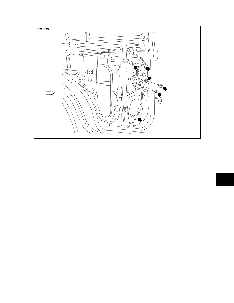
REAR DOOR GLASS AND REGULATOR
GW-19
< REMOVAL AND INSTALLATION >
C
D
E
F
G
H
I
J
L
M
A
B
GW
N
O
P
• Disconnect the connector from the regulator assembly.
INSPECTION AFTER REMOVAL
Check the regulator assembly for the following items. If a malfunction is detected, replace or grease it.
• Gear wear
• Regulator deformation
• Spring damage
• Grease condition for each sliding part
INSTALLATION
WIIA1034E