Nissan Pathfinder (2008 year). Manual - part 351


  Index      Manuals     Nissan Pathfinder (2008 year) - Service and Repair Manual


Search            copyright infringement  


Content      ..     349      350      351      352     ..


Nissan Pathfinder (2008 year). Manual - part 351


ECM

EC-925

< ECU DIAGNOSIS >

[VK56DE]

C

D

E

F

G

H

I

J

K

L

M

A

EC

N

P

O

Occasionally, certain portions of the self-diagnostic test may not be completed as a result of the customer's
normal driving pattern; the SRT will indicate “INCMP” for these items.
NOTE:
The SRT will also indicate “INCMP” if the self-diagnosis memory is erased for any reason or if the ECM mem-
ory power supply is interrupted for several hours.
If, during the state emissions inspection, the SRT indicates “CMPLT” for all test items, the inspector will con-
tinue with the emissions test. However, if the SRT indicates “INCMP” for one or more of the SRT items the
vehicle is returned to the customer untested.
NOTE:
If MIL is ON during the state emissions inspection, the vehicle is also returned to the customer untested even
though the SRT indicates “CMPLT” for all test items. Therefore, it is important to check SRT (“CMPLT”) and
DTC (No DTCs) before the inspection.
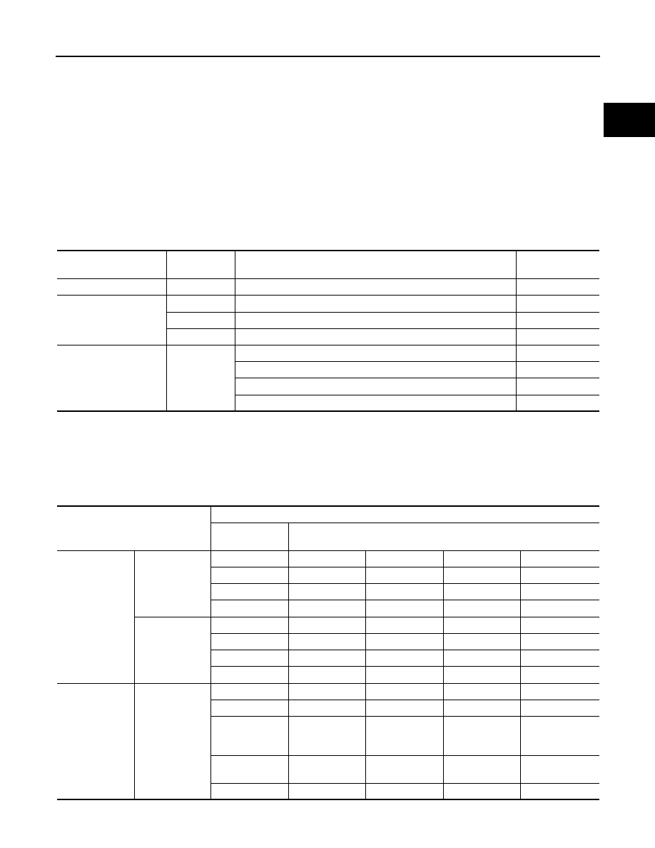
SRT Item

The table below shows required self-diagnostic items to set the SRT to “CMPLT”.

*: If completion of several SRTs is required, perform driving patterns (DTC confirmation procedure), one by one based on the priority for
models with CONSULT-III.

SRT Set Timing

SRT is set as “CMPLT” after self-diagnosis has been performed one or more times. Completion of SRT is
done regardless of whether the result is OK or NG. The set timing is different between OK and NG results and
is shown in the table below.

OK: Self-diagnosis is carried out and the result is OK.

SRT item

(CONSULT-III indication)

Performance 

Priority*

Required self-diagnostic items to set the SRT to “CMPLT”

Corresponding 

DTC No.

CATALYST

2

Three way catalyst function

P0420, P0430

EVAP SYSTEM

2

EVAP control system purge flow monitoring

P0441

1

EVAP control system

P0442

2

EVAP control system

P0456

HO2S

2

Air fuel ratio (A/F) sensor 1

P0133, P0153

Heated oxygen sensor 2

P0137, P0157

Heated oxygen sensor 2

P0138, P0158

Heated oxygen sensor 2

P0139, P0159

Self-diagnosis result

Example

Diagnosis

Ignition cycle 

 ON 

 OFF


 ON 

 OFF


 ON 

 OFF


 ON 

All OK

Case 1

P0400

OK (1)

— (1)

OK (2)

— (2)

P0402

OK (1)

— (1)

— (1)

OK (2)

P1402

OK (1)

OK (2)

— (2)

— (2)

SRT of EGR

“CMPLT”

“CMPLT”

“CMPLT”

“CMPLT”

Case 2

P0400

OK (1)

— (1)

— (1)

— (1)

P0402

— (0)

— (0)

OK (1)

— (1)

P1402

OK (1)

OK (2)

— (2)

— (2)

SRT of EGR

“INCMP”

“INCMP”

“CMPLT”

“CMPLT”

NG exists

Case 3

P0400

OK

OK

P0402

P1402

NG

NG

NG

(Consecutive 

NG)

(1st trip)

DTC

1st trip DTC

1st trip DTC

DTC

(= MIL ON)

SRT of EGR

“INCMP”

“INCMP”

“INCMP”

“CMPLT”

EC-926

< ECU DIAGNOSIS >

[VK56DE]

ECM

NG: Self-diagnosis is carried out and the result is NG.

—: Self-diagnosis is not carried out.

When all SRT related self-diagnoses showed OK results in a single cycle (Ignition OFF-ON-OFF), the SRT will
indicate “CMPLT”. 

 Case 1 above

When all SRT related self-diagnoses showed OK results through several different cycles, the SRT will indicate
“CMPLT” at the time the respective self-diagnoses have at least one OK result. 

 Case 2 above

If one or more SRT related self-diagnoses showed NG results in 2 consecutive cycles, the SRT will also indi-
cate “CMPLT”. 

 Case 3 above

The table above shows that the minimum number of cycles for setting SRT as “INCMP” is one (1) for each
self-diagnosis (Case 1 & 2) or two (2) for one of self-diagnoses (Case 3). However, in preparation for the state
emissions inspection, it is unnecessary for each self-diagnosis to be executed twice (Case 3) for the following
reasons:
• The SRT will indicate “CMPLT” at the time the respective self-diagnoses have one (1) OK result.
• The emissions inspection requires “CMPLT” of the SRT only with OK self-diagnosis results.
• When, during SRT driving pattern, 1st trip DTC (NG) is detected prior to “CMPLT” of SRT, the self-diagnosis

memory must be erased from ECM after repair.

• If the 1st trip DTC is erased, all the SRT will indicate “INCMP”.

NOTE:
SRT can be set as “CMPLT” together with the DTC(s). Therefore, DTC check must always be carried out
prior to the state emission inspection even though the SRT indicates “CMPLT”.

SRT Service Procedure

If a vehicle has failed the state emissions inspection due to one or more SRT items indicating “INCMP”, review
the flowchart diagnostic sequence on the next page.

ECM

EC-927

< ECU DIAGNOSIS >

[VK56DE]

C

D

E

F

G

H

I

J

K

L

M

A

EC

N

P

O

How to Display SRT Status

 WITH CONSULT-III

Selecting “SRT STATUS” in “DTC CONFIRMATION” mode with CONSULT-III.
For items whose SRT codes are set, a “CMPLT” is displayed on the CONSULT-III screen; for items whose
SRT codes are not set, “INCMP” is displayed.
NOTE:
Though displayed on the CONSULT-III screen, “HO2S HTR” is not SRT item.

 WITH GST

Selecting Service $01 with GST (Generic Scan Tool)

 NO TOOLS

A SRT code itself can not be displayed while only SRT status can be.

1.

Turn ignition switch ON and wait 20 seconds.

2.

SRT status is indicated as shown below.
• When all SRT codes are set, MIL lights up continuously.

*1

“How to Read DTC and 1st Trip DTC” *2

“How to Display SRT Status”

*3

“How to Set SRT Code”

PBIB2320E

EC-928

< ECU DIAGNOSIS >

[VK56DE]

ECM

• When any SRT codes are not set, MIL will flash periodically for 10 seconds.

How to Set SRT Code

To set all SRT codes, self-diagnosis for the items indicated above must be performed one or more times. Each
diagnosis may require a long period of actual driving under various conditions.

 WITH CONSULT-III

Perform corresponding DTC Confirmation Procedure one by one based on Performance Priority in the table
on “SRT Item”.

 WITHOUT CONSULT-III

The most efficient driving pattern in which SRT codes can be properly set is explained on the next page. The
driving pattern should be performed one or more times to set all SRT codes.

PBIB2317E

ECM

EC-929

< ECU DIAGNOSIS >

[VK56DE]

C

D

E

F

G

H

I

J

K

L

M

A

EC

N

P

O

Driving Pattern

• The time required for each diagnosis varies with road surface conditions, weather, altitude, individual driving

habits, etc.
Zone A refers to the range where the time, required for the diagnosis under normal conditions*, is the short-
est.
Zone B refers to the range where the diagnosis can still be performed if the diagnosis is not completed within
zone A.

*: Normal conditions refer to the following:

PBIB3622E

EC-930

< ECU DIAGNOSIS >

[VK56DE]

ECM

• Sea level
• Flat road
• Ambient air temperature: 20 - 30

°

C (68 - 86

°

F)

• Diagnosis is performed as quickly as possible under normal conditions.

Under different conditions [For example: ambient air temperature other than 20 - 30

°

C (68 - 86

°

F)], diagno-

sis may also be performed.

Pattern 1:
• The engine is started at the engine coolant temperature of 

10 to 35

°

C (14 to 95

°

F)

(where the voltage between the ECM terminal 73 and ground is 3.0 - 4.3V).

• The engine must be operated at idle speed until the engine coolant temperature is greater than 70

°

C

(158

°

F) (where the voltage between the ECM terminal 73 and ground is lower than 1.4V).

• The engine is started at the fuel tank temperature of warmer than 0

°

C (32

°

F) (where the voltage

between the ECM terminal 107 and ground is less than 4.1V).

Pattern 2:
• When steady-state driving is performed again even after it is interrupted, each diagnosis can be conducted.

In this case, the time required for diagnosis may be extended.

Pattern 3:
• Operate vehicle following the driving pattern shown in the figure.
• Release the accelerator pedal during decelerating vehicle speed

from 90 km/h (56 MPH) to 0 km/h (0 MPH).

Pattern 4:
• The accelerator pedal must be held very steady during steady-

state driving.

• If the accelerator pedal is moved, the test must be conducted all

over again.

*1: Depress the accelerator pedal until vehicle speed is 90 km/h (56
MPH), then release the accelerator pedal and keep it released for
more than 10 seconds. Depress the accelerator pedal until vehicle
speed is 90 km/h (56 MPH) again.
*2: Checking the vehicle speed with GST is advised.

Suggested Transmission Gear Position
Set the selector lever in the D position with the overdrive switch turned ON.

TEST VALUE AND TEST LIMIT

The following is the information specified in Service $06 of SAE J1979.
The test value is a parameter used to determine whether a system/circuit diagnostic test is OK or NG while
being monitored by the ECM during self-diagnosis. The test limit is a reference value which is specified as the
maximum or minimum value and is compared with the test value being monitored.
These data (test value and test limit) are specified by On Boad Monitor ID(OBDMID), Test ID (TID), Unit and
Scaling ID and can be displayed on the GST screen.
The items of the test value and test limit will be displayed with GST screen which items are provided by the
ECM. (eg., if the bank 2 is not applied on this vehicle, only the items of the bank 1 is displayed)

PBIB2244E

ECM

EC-931

< ECU DIAGNOSIS >

[VK56DE]

C

D

E

F

G

H

I

J

K

L

M

A

EC

N

P

O

Item

OBD-

MID

Self-diagnostic test item

DTC

Test value and Test 

limit

(GST display)

Description

TID

Unit and 

Scaling 

ID

HO2S

01H

Air fuel ratio (A/F) sensor 1 
(Bank 1)

P0131

83H

0BH

Minimum sensor output voltage 
for test cycle

P0131

84H

0BH

Maximum sensor output voltage 
for test cycle

P0130

85H

0BH

Minimum sensor output voltage 
for test cycle

P0130

86H

0BH

Maximum sensor output voltage 
for test cycle

P0133

87H

04H

Response rate: Response ratio 
(Lean to Rich)

P0133

88H

04H

Response rate: Response ratio 
(Rich to Lean)

P2A00

89H

84H

The amount of shift in air fuel ratio

P2A00

8AH

84H

The amount of shift in air fuel ratio

P0130

8BH

0BH

Difference in sensor output volt-
age

P0133

8CH

83H

Response gain at the limited fre-
quency

02H

Heated oxygen sensor 2 
(Bank 1)

P0138

07H

0CH

Minimum sensor output voltage 
for test cycle

P0137

08H

0CH

Maximum sensor output voltage 
for test cycle

P0138

80H

0CH

Sensor output voltage

P0139

81H

0CH

Difference in sensor output volt-
age

03H

Heated oxygen sensor 3 
(Bank 1)

P0143

07H

0CH

Minimum sensor output voltage 
for test cycle

P0144

08H

0CH

Maximum sensor output voltage 
for test cycle

P0146

80H

0CH

Sensor output voltage

P0145

81H

0CH

Difference in sensor output volt-
age

EC-932

< ECU DIAGNOSIS >

[VK56DE]

ECM

HO2S

05H

Air fuel ratio (A/F) sensor 1 
(Bank 2)

P0151

83H

0BH

Minimum sensor output voltage 
for test cycle

P0151

84H

0BH

Maximum sensor output voltage 
for test cycle

P0150

85H

0BH

Minimum sensor output voltage 
for test cycle

P0150

86H

0BH

Maximum sensor output voltage 
for test cycle

P0153

87H

04H

Response rate: Response ratio 
(Lean to Rich)

P0153

88H

04H

Response rate: Response ratio 
(Rich to Lean)

P2A03

89H

84H

The amount of shift in air fuel ratio

P2A03

8AH

84H

The amount of shift in air fuel ratio

P0150

8BH

0BH

Difference in sensor output volt-
age

P0153

8CH

83H

Response gain at the limited fre-
quency

06H

Heated oxygen sensor 2
(Bank 2)

P0158

07H

0CH

Minimum sensor output voltage 
for test cycle

P0157

08H

0CH

Maximum sensor output voltage 
for test cycle

P0158

80H

0CH

Sensor output voltage

P0159

81H

0CH

Difference in sensor output volt-
age

07H

Heated oxygen sensor 3 
(Bank2)

P0163

07H

0CH

Minimum sensor output voltage 
for test cycle

P0164

08H

0CH

Maximum sensor output voltage 
for test cycle

P0166

80H

0CH

Sensor output voltage

P0165

81H

0CH

Difference in sensor output volt-
age

CATA-
LYST

21H

Three way catalyst function 
(Bank1)

P0420

80H

01H

O2 storage index

P0420

82H

01H

Switching time lag engine exhaust 
index value

P2423

83H

0CH

Difference in 3rd O2 sensor out-
put voltage

P2423

84H

84H

O2 storage index in HC trap cata-
lyst

22H

Three way catalyst function 
(Bank2)

P0430

80H

01H

O2 storage index

P0430

82H

01H

Switching time lag engine exhaust 
index value

P2424

83H

0CH

Difference in 3rd O2 sensor out-
put voltage

P2424

84H

84H

O2 storage index in HC trap cata-
lyst

Item

OBD-

MID

Self-diagnostic test item

DTC

Test value and Test 

limit

(GST display)

Description

TID

Unit and 

Scaling 

ID


Content      ..     349      350      351      352     ..