Nissan Pathfinder (2008 year). Manual - part 345


  Index      Manuals     Nissan Pathfinder (2008 year) - Service and Repair Manual


Search            copyright infringement  


Content      ..     343      344      345      346     ..


Nissan Pathfinder (2008 year). Manual - part 345


ON BOARD REFUELING VAPOR RECOVERY (ORVR)

EC-877

< COMPONENT DIAGNOSIS >

[VK56DE]

C

D

E

F

G

H

I

J

K

L

M

A

EC

N

P

O

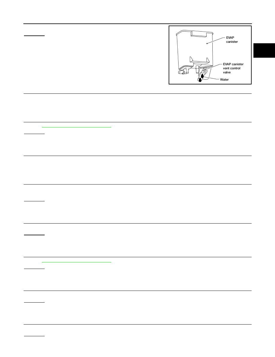
Does water drain from the EVAP canister?

Yes or No

Yes

>> GO TO 3.

No

>> GO TO 6.

3.

REPLACE EVAP CANISTER

Replace EVAP canister with a new one.

>> GO TO 4.

4.

CHECK DRAIN FILTER

Refer to 

EC-878, "Component Inspection"

.

OK or NG

OK

>> GO TO 5.

NG

>> Replace drain filter.

5.

DETECT MALFUNCTIONING PART

Check the EVAP hose between EVAP canister and drain filter for clogging or poor connection.

>> Repair or replace EVAP hose.

6.

CHECK VENT HOSES AND VENT TUBES

Check hoses and tubes between EVAP canister and refueling EVAP vapor cut valve for clogging, kink, loose-
ness and improper connection.

OK or NG

OK

>> GO TO 7.

NG

>> Repair or replace hoses and tubes.

7.

CHECK FILLER NECK TUBE

Check recirculation line for clogging, dents and cracks. 

OK or NG

OK

>> GO TO 8.

NG

>> Replace filler neck tube.

8.

CHECK REFUELING EVAP VAPOR CUT VALVE

Refer to 

EC-878, "Component Inspection"

.

OK or NG

OK

>> GO TO 9.

NG

>> Replace refueling EVAP vapor cut valve with fuel tank.

9.

CHECK FUEL FILLER TUBE

Check filler neck tube and hose connected to the fuel tank for clogging, dents and cracks.

OK or NG

OK

>> GO TO 10.

NG

>> Replace fuel filler tube.

10.

CHECK ONE-WAY FUEL VALVE-I

Check one-way valve for clogging.

OK or NG

OK

>> GO TO 11.

BBIA0558E

EC-878

< COMPONENT DIAGNOSIS >

[VK56DE]

ON BOARD REFUELING VAPOR RECOVERY (ORVR)

NG

>> Repair or replace one-way fuel valve with fuel tank.

11.

CHECK ONE-WAY FUEL VALVE-II

1.

Make sure that fuel is drained from the tank.

2.

Remove fuel filler tube and hose.

3.

Check one-way fuel valve for operation as follows.
When a stick is inserted, the valve should open, when removing
stick it should close.
Do not drop any material into the tank.

OK or NG

OK

>> INSPECTION END

NG

>> Replace fuel filler tube or replace one-way fuel valve

with fuel tank.

Component Inspection

INFOID:0000000001538008

REFUELING EVAP VAPOR CUT VALVE

 With CONSULT-III

1.

Remove fuel tank. Refer to 

FL-6, "Removal and Installation"

.

2.

Drain fuel from the tank as follows:

a.

Remove fuel feed hose located on the fuel gauge retainer. 

b.

Connect a spare fuel hose, one side to fuel gauge retainer where the hose was removed and the other
side to a fuel container.

c.

Drain fuel using “FUEL PUMP RELAY” in “ACTIVE TEST” mode with CONSULT-III.

3.

Check refueling EVAP vapor cut valve for being stuck to close as follows.
Blow air into the refueling EVAP vapor cut valve (from the end of EVAP/ORVR line hose), and check that
the air flows freely into the tank.

4.

Check refueling EVAP vapor cut valve for being stuck to open as follows.

a.

Connect vacuum pump to hose end.

b.

Remove fuel gauge retainer with fuel gauge unit.
Always replace O-ring with new one.

c.

Put fuel tank upside down.

d.

Apply vacuum pressure to hose end [

13.3 kPa (

100 mmHg, 

3.94 inHg)] with fuel gauge retainer

remaining open and check that the pressure is applicable.

 Without CONSULT-III

SEF665U

BBIA0568E

ON BOARD REFUELING VAPOR RECOVERY (ORVR)

EC-879

< COMPONENT DIAGNOSIS >

[VK56DE]

C

D

E

F

G

H

I

J

K

L

M

A

EC

N

P

O

1.

Remove fuel tank. Refer to 

FL-6, "Removal and Installation"

.

2.

Drain fuel from the tank as follows:

a.

Remove fuel gauge retainer.

b.

Drain fuel from the tank using a handy pump into a fuel container.

3.

Check refueling EVAP vapor cut valve for being stuck to close as follows.
Blow air into the refueling EVAP vapor cut valve (from the end of EVAP/ORVR line hose), and check that
the air flows freely into the tank.

4.

Check refueling EVAP vapor cut valve for being stuck to open as follows.

a.

Connect vacuum pump to hose end.

b.

Remove fuel gauge retainer with fuel gauge unit.
Always replace O-ring with new one.

c.

Put fuel tank upside down.

d.

Apply vacuum pressure to hose end [

13.3 kPa (

100 mmHg, 

3.94 inHg)] with fuel gauge retainer

remaining open and check that the pressure is applicable.

DRAIN FILTER

1.

Check visually for insect nests in the drain filter air inlet.

2.

Check visually for cracks or flaws in the appearance.

3.

Check visually for cracks or flaws in the hose.

4.

Blow air into port A and check that it flows freely out of port B.

5.

Block port B.

6.

Blow air into port A and check that there is no leakage.

7.

If NG, replace drain filter.

BBIA0568E

PBIB3641E

EC-880

< COMPONENT DIAGNOSIS >

[VK56DE]

POSITIVE CRANKCASE VENTILATION

POSITIVE CRANKCASE VENTILATION

Description

INFOID:0000000001538009

SYSTEM DESCRIPTION

This system returns blow-by gas to the intake manifold.
The positive crankcase ventilation (PCV) valve is provided to conduct crankcase blow-by gas to the intake
manifold. During partial throttle operation of the engine, the intake manifold sucks the blow-by gas through the
PCV valve. Normally, the capacity of the valve is sufficient to handle any blow-by and a small amount of venti-
lating air. The ventilating air is then drawn from the air inlet tubes into the crankcase. In this process the air
passes through the hose connecting air inlet tubes to rocker cover. Under full-throttle condition, the manifold
vacuum is insufficient to draw the blow-by flow through the valve. The flow goes through the hose connection
in the reverse direction.
On vehicles with an excessively high blow-by, the valve does not
meet the requirement. This is because some of the flow will go
through the hose connection to the air inlet tubes under all condi-
tions.

Component Inspection

INFOID:0000000001538010

PCV (POSITIVE CRANKCASE VENTILATION) VALVE

With engine running at idle, remove PCV valve from rocker cover. A
properly working valve makes a hissing noise as air passes through
it. A strong vacuum should be felt immediately when a finger is
placed over valve inlet.

PCV VALVE VENTILATION HOSE

PBIB0062E

PBIB1588E

PBIB1589E

POSITIVE CRANKCASE VENTILATION

EC-881

< COMPONENT DIAGNOSIS >

[VK56DE]

C

D

E

F

G

H

I

J

K

L

M

A

EC

N

P

O

1.

Check hoses and hose connections for leaks.

2.

Disconnect all hoses and clean with compressed air. If any hose
cannot be freed of obstructions, replace.

S-ET277

EC-882

< COMPONENT DIAGNOSIS >

[VK56DE]

REFRIGERANT PRESSURE SENSOR

REFRIGERANT PRESSURE SENSOR

Component Description

INFOID:0000000001538011

The refrigerant pressure sensor (1) is installed at the condenser of
the air conditioner system. The sensor uses an electrostatic volume
pressure transducer to convert refrigerant pressure to voltage. The
voltage signal is sent to ECM, and ECM controls cooling fan system.

Diagnosis Procedure

INFOID:0000000001538012

1.

CHECK REFRIGERANT PRESSURE SENSOR OVERALL FUNCTION

1.

Start engine and warm it up to normal operating temperature.

2.

Turn A/C switch and blower fan switch ON.

3.

Check voltage between ECM terminal 70 and ground with CON-
SULT-III or tester.

OK or NG

OK

>> INSPECTION END

NG

>> GO TO 2.

2.

CHECK GROUND CONNECTIONS

1.

Turn A/C switch and blower fan switch OFF.

2.

Turn ignition switch OFF.

3.

Loosen and retighten three ground screws on the body.

ALBIA0357ZZ

PBIB2657E

Voltage: 1.0 - 4.0V

PBIB1188E

REFRIGERANT PRESSURE SENSOR

EC-883

< COMPONENT DIAGNOSIS >

[VK56DE]

C

D

E

F

G

H

I

J

K

L

M

A

EC

N

P

O

Refer to 

EC-565, "Ground Inspection"

.

OK or NG

OK

>> GO TO 3.

NG

>> Repair or replace ground connections.

3.

CHECK REFRIGERANT PRESSURE SENSOR POWER SUPPLY CIRCUIT

1.

Disconnect refrigerant pressure sensor (1) harness connector.

2.

Turn ignition switch ON.

3.

Check voltage between refrigerant pressure sensor terminal 1
and ground with CONSULT-III or tester.

OK or NG

OK

>> GO TO 5.

NG

>> GO TO 4.

4.

DETECT MALFUNCTIONING PART

Check the following.
• Harness connectors E5, F14
• Harness for open or short between ECM and refrigerant pressure sensor

>> Repair harness or connectors.

5.

CHECK REFRIGERANT PRESSURE SENSOR GROUND CIRCUIT FOR OPEN AND SHORT

1.

Turn ignition switch OFF.

2.

Disconnect ECM harness connector.

3.

Check harness continuity between refrigerant pressure sensor terminal 3 and ECM terminal 67.
Refer to Wiring Diagram.

4.

Also check harness for short to ground and short to power.

OK or NG

OK

>> GO TO 7.

NG

>> GO TO 6.

BBIA0539E

ALBIA0357ZZ

Voltage: Approximately 5V

PBIB0188E

Continuity should exist.

EC-884

< COMPONENT DIAGNOSIS >

[VK56DE]

REFRIGERANT PRESSURE SENSOR

6.

DETECT MALFUNCTIONING PART

Check the following.
• Harness connectors E5, F14
• Harness for open or short between ECM and refrigerant pressure sensor

>> Repair open circuit or short to ground or short to power in harness or connectors.

7.

CHECK REFRIGERANT PRESSURE SENSOR INPUT SIGNAL CIRCUIT FOR OPEN AND SHORT

1.

Check harness continuity between ECM terminal 70 and refrigerant pressure sensor terminal 2.
Refer to Wiring Diagram.

2.

Also check harness for short to ground and short to power.

OK or NG

OK

>> GO TO 9.

NG

>> GO TO 8.

8.

DETECT MALFUNCTIONING PART

Check the following.
• Harness connectors E5, F14
• Harness for open or short between ECM and refrigerant pressure sensor

>> Repair open circuit or short to ground or short to power in harness or connectors.

9.

CHECK INTERMITTENT INCIDENT

Refer to 

GI-51, "Intermittent Incident"

.

OK or NG

OK

>> Replace refrigerant pressure sensor.

NG

>> Repair or replace. 

Continuity should exist.


Content      ..     343      344      345      346     ..