Nissan Pathfinder (2008 year). Manual - part 295


  Index      Manuals     Nissan Pathfinder (2008 year) - Service and Repair Manual


Search            copyright infringement  


Content      ..     293      294      295      296     ..


Nissan Pathfinder (2008 year). Manual - part 295


PRECAUTIONS

EC-477

< PRECAUTION >

[VQ40DE]

C

D

E

F

G

H

I

J

K

L

M

A

EC

N

P

O

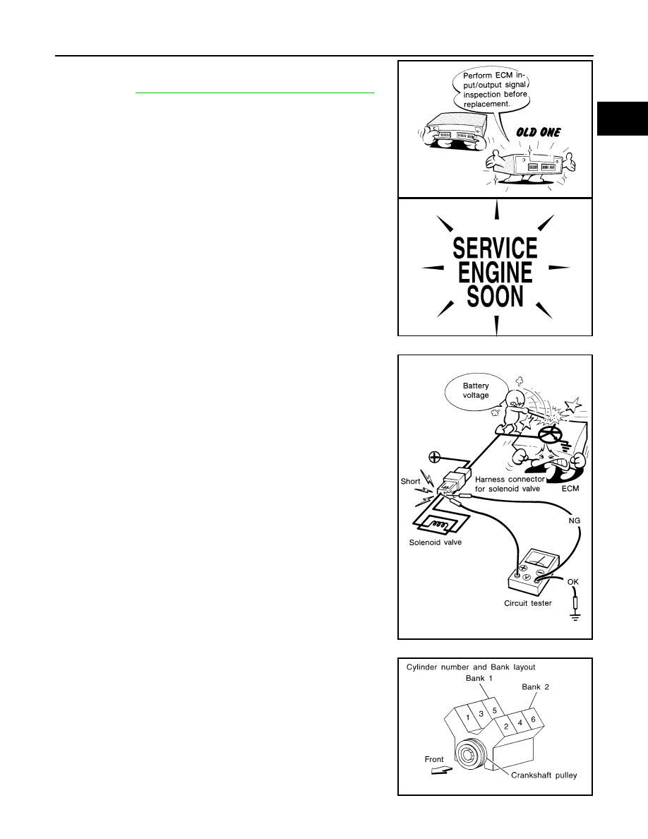
• Before replacing ECM, perform “ECM Terminals and Refer-

ence Value” inspection and make sure ECM functions prop-
erly. Refer to 

EC-422, "ECM Terminal and Reference Value"

.

• Handle mass air flow sensor carefully to avoid damage.
• Do not clean mass air flow sensor with any type of detergent.
• Do not disassemble electric throttle control actuator.
• Even a slight leak in the air intake system can cause serious

incidents.

• Do not shock or jar the camshaft position sensor (PHASE),

crankshaft position sensor (POS).

• After performing each TROUBLE DIAGNOSIS, perform DTC

Confirmation Procedure or Overall Function Check.
The DTC should not be displayed in the DTC Confirmation
Procedure if the repair is completed. The Overall Function
Check should be a good result if the repair is completed.

• When measuring ECM signals with a circuit tester, never allow

the two tester probes to contact.
Accidental contact of probes will cause a short circuit and
damage the ECM power transistor.

• Do not use ECM ground terminals when measuring input/out-

put voltage. Doing so may result in damage to the ECM's tran-
sistor. Use a ground other than ECM terminals, such as the
ground.

• B1 indicates the bank 1, B2 indicates the bank 2 as shown in

the figure.

MEF040D

SEF217U

SEF348N

SEC893C

EC-478

< PRECAUTION >

[VQ40DE]

PRECAUTIONS

• Do not operate fuel pump when there is no fuel in lines.
• Tighten fuel hose clamps to the specified torque.

• Do not depress accelerator pedal when starting.
• Immediately after starting, do not rev up engine unnecessar-

ily.

• Do not rev up engine just prior to shutdown.

• When installing C.B. ham radio or a mobile phone, be sure to

observe the following as it may adversely affect electronic
control systems depending on installation location.

Keep the antenna as far as possible from the electronic con-

trol units.

Keep the antenna feeder line more than 20 cm (8 in) away

from the harness of electronic controls.
Do not let them run parallel for a long distance.

Adjust the antenna and feeder line so that the standing-wave

radio can be kept smaller.

Be sure to ground the radio to vehicle body.

BBIA0529E

SEF709Y

SEF708Y

PBIB1512E

PREPARATION

EC-479

< PREPARATION >

[VQ40DE]

C

D

E

F

G

H

I

J

K

L

M

A

EC

N

P

O

PREPARATION

PREPARATION

Special Service Tool

INFOID:0000000001366285

The actual shapes of Kent-Moore tools may differ from those of special service tools illustrated here.

Tool number
(Kent-Moore No.)
Tool name

Description

EG17650301
(J-33984-A)
Radiator cap tester 
adapter

Adapting radiator cap tester to radiator cap and ra-
diator filler neck
a: 28 (1.10) dia.
b: 31.4 (1.236) dia.
c: 41.3 (1.626) dia.
Unit: mm (in)

(J-44321)
Fuel pressure gauge 
kit

Checking fuel pressure

(J-44321-6)
Fuel pressure adapter

Connecting fuel pressure gauge to quick connec-
tor type fuel lines.

(J-45488)
Quick connector re-
lease


Remove fuel tube quick connectors in engine 
room

S-NT564

LEC642

LBIA0376E

PBIC0198E

EC-480

< PREPARATION >

[VQ40DE]

PREPARATION

Commercial Service Tool

INFOID:0000000001366286

Tool name
(Kent-Moore No.)

Description

Leak detector 
i.e.: (J-41416)

Locating the EVAP leak

EVAP service port 
adapter
i.e.: (J-41413-OBD)

Applying positive pressure through EVAP service 
port

Fuel filler cap adapter
i.e.: (MLR-8382)

Checking fuel tank vacuum relief valve opening 
pressure

Socket wrench

Removing and installing engine coolant tempera-
ture sensor

Oxygen sensor thread 
cleaner
i.e.: (J-43897-18)
(J-43897-12)

Reconditioning the exhaust system threads before 
installing a new oxygen sensor. Use with anti-
seize lubricant shown below.
a: 18 mm diameter with pitch 1.5 mm for Zirco-
nia Oxygen Sensor
b: 12 mm diameter with pitch 1.25 mm for Tita-
nia Oxygen Sensor

Anti-seize lubricant 

i.e.: (Permatex

TM


133AR or equivalent 
meeting MIL specifica-
tion MIL-A-907)

Lubricating oxygen sensor thread cleaning tool 
when reconditioning exhaust system threads.

S-NT703

S-NT704

S-NT815

S-NT705

AEM488

S-NT779

FUEL PRESSURE

EC-481

< ON-VEHICLE MAINTENANCE >

[VQ40DE]

C

D

E

F

G

H

I

J

K

L

M

A

EC

N

P

O

ON-VEHICLE MAINTENANCE

FUEL PRESSURE

Fuel Pressure Check

INFOID:0000000001366444

FUEL PRESSURE RELEASE

 With CONSULT-III

1.

Turn ignition switch ON.

2.

Perform “FUEL PRESSURE RELEASE” in “WORK SUPPORT” mode with CONSULT-III.

3.

Start engine.

4.

After engine stalls, crank it two or three times to release all fuel pressure.

5.

Turn ignition switch OFF.

 Without CONSULT-III

1.

Remove fuel pump fuse located in IPDM E/R.

2.

Start engine.

3.

After engine stalls, crank it two or three times to release all fuel
pressure.

4.

Turn ignition switch OFF.

5.

Reinstall fuel pump fuse after servicing fuel system.

FUEL PRESSURE CHECK

CAUTION:

Be careful not to scratch or get the fuel hose connection area dirty when servicing, so that the quick
connector o-ring maintains sealability.
NOTE:
• Prepare pans or saucers under the disconnected fuel line because the fuel may spill out. The fuel

pressure cannot be completely released because R51 models do not have fuel return system.

• Use Fuel Pressure Gauge Kit J-44321 and Fuel Pressure Adapter J-44321-6 to check fuel pressure.
1.

Release fuel pressure to zero. Refer to "FUEL PRESSURE RELEASE".

2.

Remove fuel hose using Quick Connector Release J-45488. Refer to 

EM-29

.

• Do not twist or kink fuel hose because it is plastic hose.
• Do not remove fuel hose from quick connector.
• Keep fuel hose connections clean.

3.

Install Fuel Pressure Adapter J-44321-6 and Fuel Pressure
Gauge (from kit J-44321) as shown in figure.
• Do not distort or bend fuel rail tube when installing fuel pres-

sure gauge adapter.

• When reconnecting fuel hose, check the original fuel hose for

damage and abnormality.

4.

Turn ignition switch ON (reactivate fuel pump), and check for
fuel leakage.

5.

Start engine and check for fuel leakage.

6.

Read the indication of fuel pressure gauge.
• During fuel pressure check, check for fuel leakage from fuel

connection every 3 minutes.

7.

If result is unsatisfactory, go to next step.

BBIA0534E

At idling:

Approximately 350 kPa (3.57 kg/cm

2

, 51 psi)

BBIA0535E

EC-482

< ON-VEHICLE MAINTENANCE >

[VQ40DE]

FUEL PRESSURE

8.

Check the following.
• Fuel hoses and fuel tubes for clogging
• Fuel filter for clogging
• Fuel pump
• Fuel pressure regulator for clogging
If OK, replace fuel pressure regulator.
If NG, repair or replace.

9.

Before disconnecting Fuel Pressure Gauge and Fuel Pressure Adapter J-44321-6, release fuel pressure
to zero. Refer to "FUEL PRESSURE RELEASE".

EVAP LEAK CHECK

EC-483

< ON-VEHICLE MAINTENANCE >

[VQ40DE]

C

D

E

F

G

H

I

J

K

L

M

A

EC

N

P

O

EVAP LEAK CHECK

How to Detect Fuel Vapor Leakage

INFOID:0000000001366385

CAUTION:

• Never use compressed air or a high pressure pump.
• Do not exceed 4.12 kPa (0.042 kg/cm

2

, 0.6 psi) of pressure in EVAP system.

NOTE:
• Do not start engine.
• Improper installation of EVAP service port adapter to the EVAP service port may cause a leak.

 WITH CONSULT-III

1.

Attach the EVAP service port adapter securely to the EVAP service port.

2.

Also attach the pressure pump and hose to the EVAP service port adapter.

3.

Turn ignition switch ON.

4.

Select the “EVAP SYSTEM CLOSE” of “WORK SUPPORT MODE” with CONSULT-III.

5.

Touch “START”. A bar graph (Pressure indicating display) will appear on the screen.

6.

Apply positive pressure to the EVAP system until the pressure indicator reaches the middle of the bar
graph.

7.

Remove EVAP service port adapter and hose with pressure pump.

8.

Locate the leak using a leak detector. Refer to 

EC-46, "Descrip-

tion"

.

 WITHOUT CONSULT-III

1.

Attach the EVAP service port adapter securely to the EVAP ser-
vice port.

2.

Also attach the pressure pump with pressure gauge to the EVAP
service port adapter.

3.

Apply battery voltage between the terminals of EVAP canister
vent control valve (3) to make a closed EVAP system.

-

Fuel filler pipe (top of frame view) (1)

-

EVAP control system pressure sensor (2)

-

EVAP ccanister (4)

-

Drain filter (5)

-

: Vehicle front

4.

To locate the leak, deliver positive pressure to the EVAP system
until pressure gauge points reach 1.38 to 2.76 kPa (0.014 to
0.028 kg/cm

2

, 0.2 to 0.4 psi).

5.

Remove EVAP service port adapter and hose with pressure
pump.

6.

Locate the leak using a leak detector. Refer to 

EC-46, "Description"

.

SEF200U

SEF462UA

AWBIA0134ZZ

EC-484

< ON-VEHICLE REPAIR >

[VQ40DE]

EVAP CANISTER

ON-VEHICLE REPAIR

EVAP CANISTER

Component Inspection

INFOID:0000000001366383

EVAP CANISTER

Check EVAP canister as follows:

1.

Block port B.

2.

Blow air into port A and check that it flows freely out of port C.

3.

Release blocked port B.

4.

Apply vacuum pressure to port B and check that vacuum pres-
sure exists at the ports A and C.

5.

Block port A and B.

6.

Apply pressure to port C and check that there is no leakage.

Removal and Installation

INFOID:0000000001366384

EVAP CANISTER

Tighten EVAP canister as shown in the figure.

EVAP CANISTER VENT CONTROL VALVE

1.

Turn EVAP canister vent control valve counterclockwise.

2.

Remove the EVAP canister vent control valve.

Always replace O-ring with a new one.

PBIB2568E

BBIA0566E

BBIA0567E


Content      ..     293      294      295      296     ..