Nissan Pathfinder (2008 year). Manual - part 258
P0171, P0174 FUEL INJECTION SYSTEM FUNCTION
EC-181
< COMPONENT DIAGNOSIS >
[VQ40DE]
C
D
E
F
G
H
I
J
K
L
M
A
EC
N
P
O
2.
Listen for an exhaust gas leak before three way catalyst (manifold).
OK or NG
OK
>> GO TO 2.
NG
>> Repair or replace.
2.
CHECK FOR INTAKE AIR LEAK
1.
Listen for an intake air leak after the mass air flow sensor.
2.
Check PCV hose connection.
OK or NG
OK
>> GO TO 3.
NG
>> Repair or replace.
3.
CHECK A/F SENSOR 1 INPUT SIGNAL CIRCUIT
1.
Turn ignition switch OFF.
2.
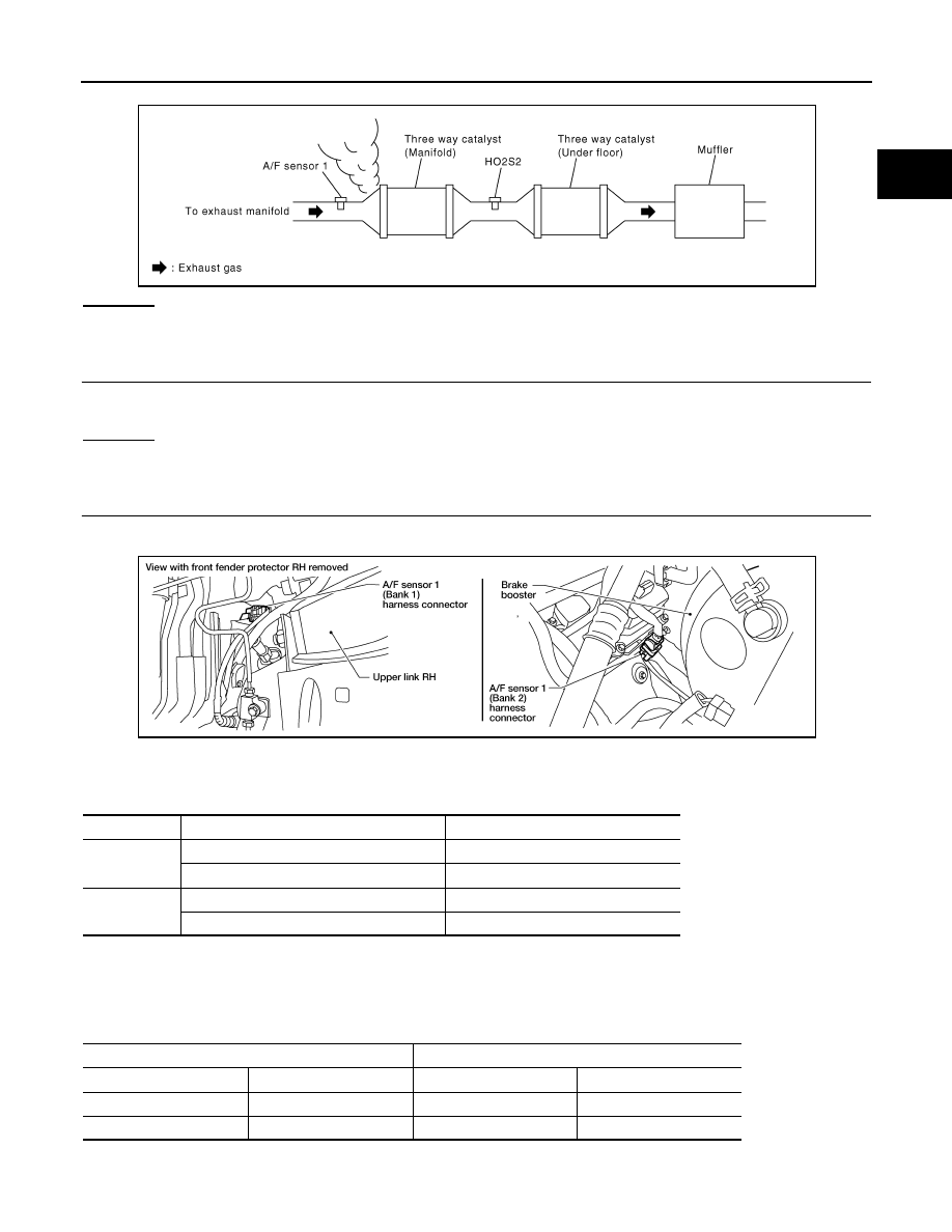
Disconnect corresponding A/F sensor 1 harness connector.
3.
Disconnect ECM harness connector.
4.
Check harness continuity between A/F sensor 1 terminal and ECM terminal as follows.
Refer to Wiring Diagram.
5.
Check harness continuity between the following terminals and ground.
Refer to Wiring Diagram.
PBIB1216E
A/F sensor 1 terminal
ECM terminal
Bank 1
1
35
2
56
Bank 2
1
16
2
75
Continuity should exist.
Bank 1
Bank 2
A/F sensor 1 terminal
ECM terminal
A/F sensor 1 terminal
ECM terminal
1
35
1
16
2
56
2
75
Continuity should not exist.
BBIA0544E