Nissan Pathfinder (2008 year). Manual - part 186


  Index      Manuals     Nissan Pathfinder (2008 year) - Service and Repair Manual


Search            copyright infringement  


Content      ..     184      185      186      187     ..


Nissan Pathfinder (2008 year). Manual - part 186


DLN-72

< COMPONENT DIAGNOSIS >

[TRANSFER: ATX14B]

P1826 TRANSFER FLUID TEMPERATURE
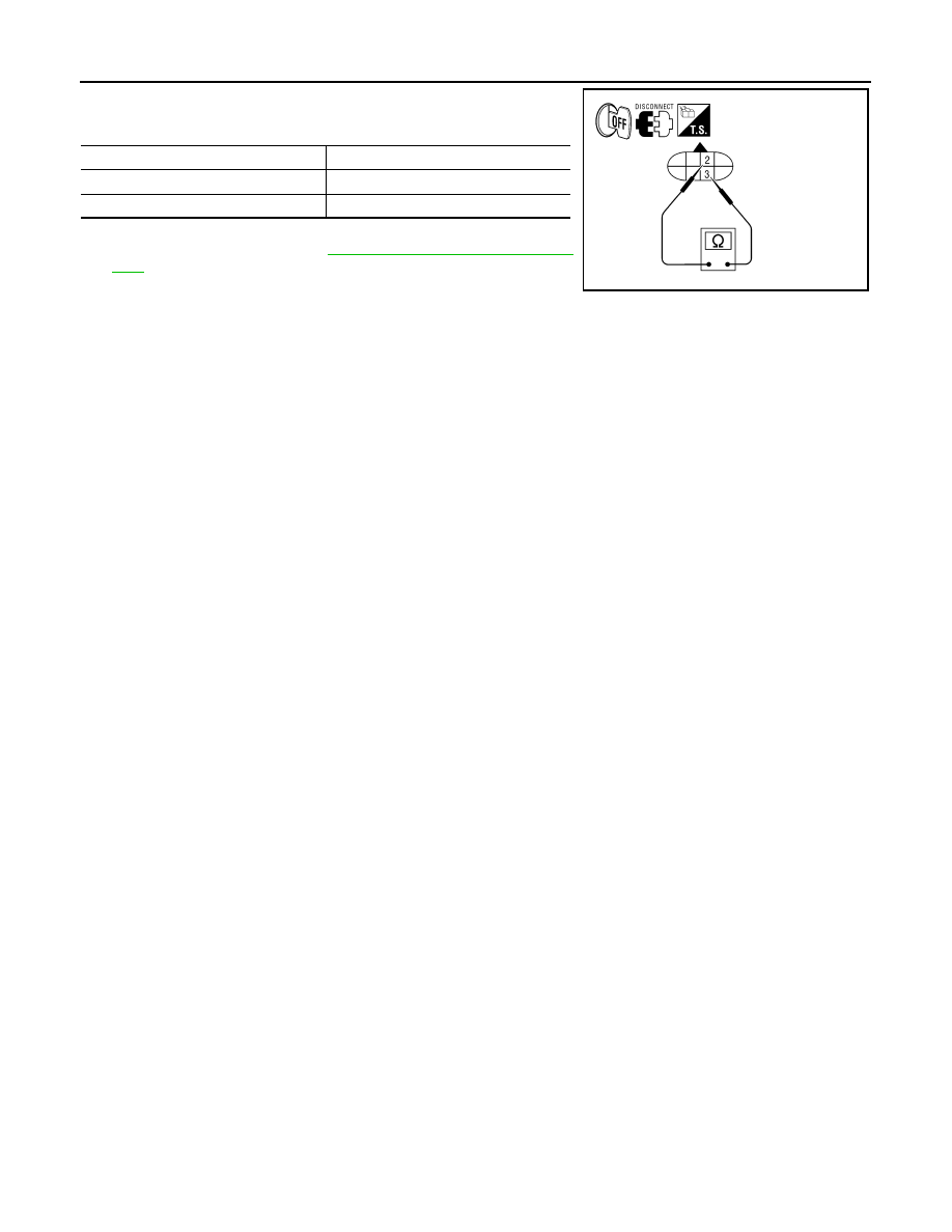
3.

Check resistance between transfer terminal cord assembly ter-
minals 2 and 3.

4.

If the inspection results are abnormal replace the transfer fluid
temperature sensor. Refer to 

DLN-18, "Component Parts Loca-

tion"

.

Temperature 

°

C (

°

F)

Resistance (Approx.)

20 (68)

2.5 k

80 (176)

0.3 k

WDIA0188E

P1827 CLUTCH PRESSURE SWITCH

DLN-73

< COMPONENT DIAGNOSIS >

[TRANSFER: ATX14B]

C

E

F

G

H

I

J

K

L

M

A

B

DLN

N

O

P

P1827 CLUTCH PRESSURE SWITCH

Description

INFOID:0000000001728396

Improper signal from the clutch pressure switch is input due to open or short circuit.  Also, a malfunction may
have occured in clutch pressure switch or hydraulic circuit.

DTC Logic

INFOID:0000000001728397

DTC DETECTION LOGIC

DTC CONFIRMATION PROCEDURE

1.

DTC CONFIRMATION PROCEDURE

1.

Turn ignition switch ON.

2.

Perform self-diagnosis.

Is DTC P1827 displayed?

YES

>> Perform diagnosis procedure. Refer to 

DLN-73, "Diagnosis Procedure"

.

NO

>> Inspection End.

Diagnosis Procedure

INFOID:0000000001728398

1.

CHECK CLUTCH PRESSURE SWITCH SIGNAL

 With CONSULT-III

1.

Start engine.

2.

Select DATA MONITOR mode for ALL MODE AWD/4WD with CONSULT-III.

3.

Read out ON/OFF switching action of the CL PRES SW while operating 4WD shift switch.

 Without CONSULT-III

1.

Start engine.

2.

Check voltage between transfer control unit harness connector
terminals and ground.

Are inspection results normal?

DTC

CONSULT-III

Diagnostic item is detected when...

Reference

[P1827]

CLUTCH PRES SW

• Improper signal from clutch pressure 

switch is input due to open or short cir-
cuit.

• Malfunction occurs in clutch pressure 

switch or hydraulic circuit.

Refer to 

DLN-73

.

Condition

Display value

• Ignition switch: ON
• A/T selector lever D position

4WD shift switch: AUTO or 4H (Wait 
function is not operating.)

ON

Ignition switch: ON

4WD shift switch: 2WD (Wait function 
is not operating.)

OFF

Connector

Terminal

Condition

Voltage 

(Approx.)

M153

34 - 

Ground

• Ignition switch: ON
• A/T selector lever D 

position

4WD shift switch: 
AUTO or 4H (Wait 
function is not op-
erating.)

0V

Ignition switch: ON

4WD shift switch: 
2WD (Wait function 
is not operating.)

Battery 
voltage

SDIA2746E

DLN-74

< COMPONENT DIAGNOSIS >

[TRANSFER: ATX14B]

P1827 CLUTCH PRESSURE SWITCH

YES

>> GO TO 5.

NO

>> GO TO 2.

2.

CHECK HARNESS BETWEEN TRANSFER CONTROL UNIT AND CLUTCH PRESSURE SWITCH

1.

Turn ignition switch OFF. (Stay for at least 5 seconds.)

2.

Disconnect transfer control unit harness connector and the transfer terminal cord assembly harness con-
nector.

3.

Check continuity between transfer control unit harness connec-
tor M153 terminal 34 and transfer terminal cord assembly har-
ness connector F56 terminal 7

Also check harness for short to ground and short to power.

Are inspection results normal?

YES 

>> GO TO 3.

NO

>> Repair or replace damaged parts.

3.

CHECK TRANSFER CONTROL UNIT

Check transfer control unit input/output signal. Refer to 

DLN-83, "Reference Value"

.

Are inspection results normal?

YES

>> GO TO 4.

NO

>> Check transfer control unit pin terminals for damage or loose connection with the harness connec-

tor. If any items are damaged, repair or replace damaged parts.

4.

CHECK CLUTCH PRESSURE SWITCH

1.

Turn ignition switch OFF. (Stay for at least 5 seconds.)

2.

Remove clutch pressure switch. Refer to 

DLN-18, "Component Parts Location"

.

3.

Push and release clutch pressure switch and check continuity
between terminal 7 and ground.

Are inspection results normal?

YES 

>> GO TO 5.

NO

>> Replace clutch pressure switch.

5.

CHECK DTC

Perform the self-diagnosis, after driving a vehicle for a while.

Are inspection results normal?

YES

>> GO TO 6.

NO

>> Replace transfer control unit. Refer to 

DLN-135, "Removal and Installation"

.

6.

CRUISE TEST

Perform cruise test. Refer to 

DLN-9, "Preliminary Check"

.

Are inspection results normal?

YES

>> Inspection End.

NO

>> Perform the applicable trouble diagnosis.

Component Inspection

INFOID:0000000001728399

1.

Turn ignition switch OFF. (Stay for at least 5 seconds.)

2.

Remove clutch pressure switch. Refer to 

DLN-18, "Component Parts Location"

.

Continuity should exist.

SDIA2747E

Terminal

Condition

Continuity

7 - 

Ground

Push clutch pressure switch

Yes

Release clutch pressure switch

No

WDIA0171E

P1827 CLUTCH PRESSURE SWITCH

DLN-75

< COMPONENT DIAGNOSIS >

[TRANSFER: ATX14B]

C

E

F

G

H

I

J

K

L

M

A

B

DLN

N

O

P

3.

Push and release clutch pressure switch and check continuity
between terminal 7 and ground.

4.

If the inspection results are abnormal replace the clutch pres-
sure switch.

Terminal

Condition

Continuity

7 - Ground

Push clutch pressure switch

Yes

Release clutch pressure switch

No

WDIA0171E

DLN-76

< COMPONENT DIAGNOSIS >

[TRANSFER: ATX14B]

P1828 LINE PRESSURE SWITCH

P1828 LINE PRESSURE SWITCH

Description

INFOID:0000000001728400

Improper signal from line pressure switch is input due to open or short circuit.  Also, a malfunction may have
occured in the line pressure switch or hydraulic circuit.

DTC Logic

INFOID:0000000001728401

DTC DETECTION LOGIC

DTC CONFIRMATION PROCEDURE

1.

DTC CONFIRMATION PROCEDURE

1.

Turn ignition switch ON.

2.

Perform self-diagnosis.

Is DTC P1828 displayed?

YES

>> Perform diagnosis procedure. Refer to 

DLN-76, "Diagnosis Procedure"

.

NO

>> Inspection End.

Diagnosis Procedure

INFOID:0000000001728402

1.

CHECK LINE PRESSURE SWITCH SIGNAL

 With CONSULT-III

1.

Start engine.

2.

Select DATA MONITOR mode for ALL MODE AWD/4WD with CONSULT-III.

3.

Read out ON/OFF switching action of LINE PRES SW while operating 4WD shift switch.

 Without CONSULT-III

1.

Start engine.

2.

Check voltage between transfer control unit harness connector
terminals and ground.

DTC

CONSULT-III

Diagnostic item is detected when...

Reference

[P1828]

LINE PRES SW

• Improper signal from line pressure 

switch is input due to open or short cir-
cuit.

• Malfunction occurs in line pressure 

switch or hydraulic circuit.

Refer to 

DLN-76

.

Condition

Display value

• A/T selector lever D position
• 4WD shift switch: AUTO

ON

• Except the above
• The vehicle has been left 

at room temperature for 5 
minutes and more with ig-
nition switch in OFF posi-
tion.

• Ignition switch: ON
• A/T selector lever: P or N position
• 4WD shift switch: other than 

AUTO

OFF

SDIA2751E

P1828 LINE PRESSURE SWITCH

DLN-77

< COMPONENT DIAGNOSIS >

[TRANSFER: ATX14B]

C

E

F

G

H

I

J

K

L

M

A

B

DLN

N

O

P

Are inspection results normal?

YES

>> GO TO 5.

NO

>> GO TO 2.

2.

CHECK HARNESS BETWEEN TRANSFER CONTROL UNIT AND LINE PRESSURE SWITCH

1.

Turn ignition switch OFF. (Stay for at least 5 seconds.)

2.

Disconnect transfer control unit harness connector and the transfer terminal cord assembly harness con-
nector.

3.

Check continuity between transfer control unit harness connec-
tor M153 terminal 35 and transfer terminal cord assembly har-
ness connector F56 terminal 1.

Also check harness for short to ground and short to power.

Are inspection results normal?

YES 

>> GO TO 3.

NO

>> Repair or replace damaged parts.

3.

CHECK TRANSFER CONTROL UNIT

Check transfer control unit input/output signal. Refer to 

DLN-83, "Reference Value"

.

Are inspection results normal?

YES

>> GO TO 4.

NO

>>

Check the following. If any items are damaged, repair or replace damaged parts.

• Transfer control unit pin terminals for damage or loose connection with harness connector.
• Transfer control unit. Refer to 

DLN-135, "Removal and Installation"

.

4.

CHECK LINE PRESSURE SWITCH

1.

Turn ignition switch OFF. (Stay for at least 5 seconds.)

2.

Remove line pressure switch. Refer to 

DLN-18, "Component Parts Location"

.

3.

Push and release line pressure switch and check continuity
between terminal 1 and ground.

Are inspection results normal?

YES 

>> GO TO 5.

NO

>> Replace line pressure switch.

5.

CHECK DTC

Perform the self-diagnosis, after driving a vehicle for a while.

Connector

Terminal

Condition

Voltage 

(Approx.)

M153

35 - 

Ground

• A/T selector lever D 

position

4WD shift switch:  
AUTO

0V

• Except the above
• The vehicle has 

been left at room 
temperature for 5 
minutes and more 
with ignition switch 
in OFF position.

• Ignition switch: 

ON

• A/T selector le-

ver: P or N posi-
tion

• 4WD shift 

switch: other 
than AUTO

Battery 
voltage

Continuity should exist.

SDIA2752E

Terminal

Condition

Continuity

1 - 

Ground

Push line pressure switch

Yes

Release line pressure switch

No

WDIA0172E

DLN-78

< COMPONENT DIAGNOSIS >

[TRANSFER: ATX14B]

P1828 LINE PRESSURE SWITCH

Are inspection results normal?

YES

>> GO TO 6.

NO

>> Replace transfer control unit.

6.

CRUISE TEST

Perform cruise test. Refer to 

DLN-9, "Preliminary Check"

.

Are inspection results normal?

YES

>> Inspection End.

NO

>> Perform the applicable trouble diagnosis.

Component Inspection

INFOID:0000000001728403

1.

Turn ignition switch OFF. (Stay for at least 5 seconds.)

2.

Remove line pressure switch. Refer to 

DLN-18, "Component Parts Location"

.

3.

Push and release line pressure switch and check continuity
between terminal 1 and ground.

4.

If the inspection results are abnormal, replace the line pressure
switch.

Terminal

Condition

Continuity

1 - Ground

Push line pressure switch

Yes

Release line pressure switch

No

WDIA0172E

P1829 THROTTLE POSITION SIGNAL (ECM)

DLN-79

< COMPONENT DIAGNOSIS >

[TRANSFER: ATX14B]

C

E

F

G

H

I

J

K

L

M

A

B

DLN

N

O

P

P1829 THROTTLE POSITION SIGNAL (ECM)

Description

INFOID:0000000001728404

Malfunction is detected in accelerator pedal position signal that is output from ECM through CAN communica-
tion.  Also, the signal voltage from accelerator pedal position sensor may be abnormally high or low.

DTC Logic

INFOID:0000000001728405

DTC DETECTION LOGIC

DTC CONFIRMATION PROCEDURE

1.

DTC CONFIRMATION PROCEDURE

1.

Turn ignition switch ON.

2.

Perform self-diagnosis.

Is DTC P1829 displayed?

YES

>> Perform diagnosis procedure. Refer to 

DLN-79, "Diagnosis Procedure"

.

NO

>> Inspection End.

Diagnosis Procedure

INFOID:0000000001728406

1.

CHECK DTC WITH ECM

Perform self-diagnosis with ECM. Refer to 

EC-542, "CONSULT-III Function (ENGINE)"

.

Is any malfunction detected by self-diagnosis?

YES

>> Check the malfunctioning system.

NO

>> GO TO 2.

2.

CHECK TRANSFER CONTROL UNIT

Check transfer control unit input/output signal. Refer to 

DLN-83, "Reference Value"

.

Are inspection results normal?

YES

>> GO TO 3.

NO

>> Check transfer control unit pin terminals for damage or loose connection with harness connector.

If any items are damaged, repair or replace damaged parts.

3.

CHECK DTC

Perform the self-diagnosis, after driving a vehicle for a while.

Are inspection results normal?

YES

>> Inspection End.

NO

>> Perform self-diagnosis with ECM again.

DTC

CONSULT-III

Diagnostic item is detected when...

Reference

[P1829]

THROTTLE POSI SEN

• Malfunction is detected in accelerator 

pedal position signal that is output 
from ECM through CAN communica-
tion.

• Signal voltage from accelerator pedal 

position sensor is abnormally high or 
low.

Refer to 

DLN-79

.


Content      ..     184      185      186      187     ..