Nissan Pathfinder (2008 year). Manual - part 153
BCM (BODY CONTROL MODULE)
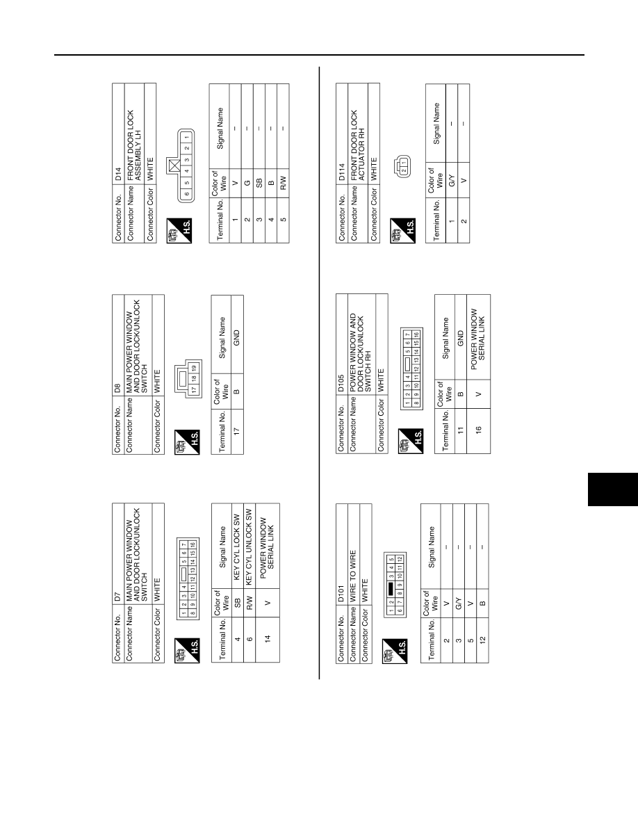
DLK-125
< ECU DIAGNOSIS >
[WITH INTELLIGENT KEY SYSTEM]
C
D
E
F
G
H
I
J
L
M
A
B
DLK
N
O
P
ALKIA0988GB
|
|
|
BCM (BODY CONTROL MODULE) DLK-125 < ECU DIAGNOSIS > [WITH INTELLIGENT KEY SYSTEM] C D E F G H I J L M A B DLK N O P ALKIA0988GB |