Nissan Pathfinder (2007 year). Manual - part 355


  Index      Manuals     Nissan Pathfinder (2007 year) - Service and Repair Manual


Search            copyright infringement  


Content      ..     353      354      355      356     ..


Nissan Pathfinder (2007 year). Manual - part 355


SUNROOF

RF-17

C

D

E

F

G

H

J

K

L

M

A

B

RF

2007 Pathfinder

Trouble Diagnosis Chart by Symptom

EIS007TC

BCM Power Supply and Ground Circuit Check

EIS007TD

Refer to 

BCS-16, "BCM Power Supply and Ground Circuit Check"

 .

Sunroof Switch System Check

EIS007TE

1. 

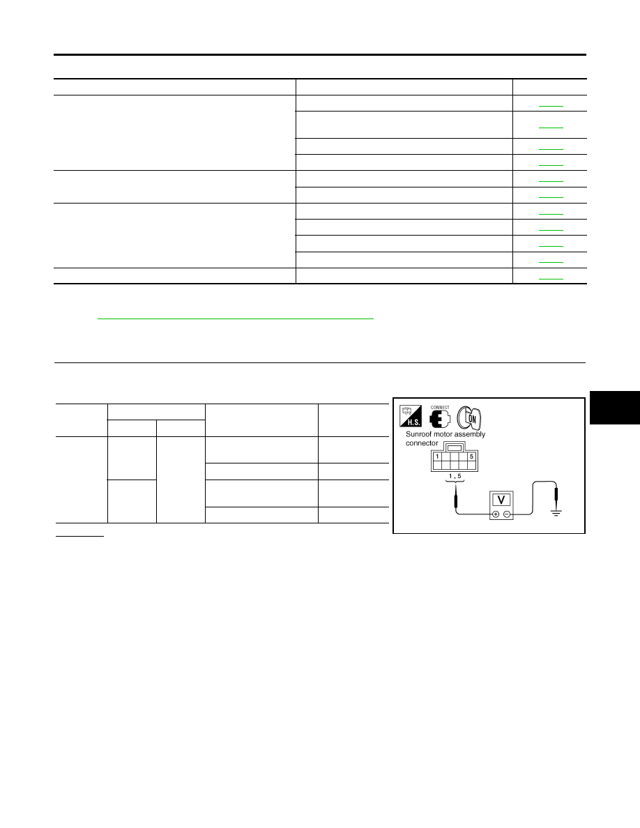
SUNROOF SWITCH INPUT SIGNAL CHECK 

1.

Turn ignition switch ON.

2.

Check voltage between sunroof motor assembly connector and ground.

OK or NG

OK

>> Sunroof switch input signal circuits are OK.

NG

>> GO TO 2.

Symptom

Diagnostic procedure and repair order

Refer to page

Sunroof does not operate.

1. BCM power supply and ground circuit check

RF-17

2. Sunroof motor assembly power supply and ground 
circuit check

RF-19

3. Sunroof switch system check

RF-17

4. Replace sunroof motor assembly

RF-25

Motor does not stop at the sunroof fully-open or fully-closed 
position.

1. Initialization procedure check

RF-11

2. Replace sunroof motor assembly

RF-25

Retained power operation does not operate properly.

1. Check the retained power operation mode setting

RF-11

2. BCM power supply and ground circuit check

RF-17

3. Door switch check

RF-20

4. Replace sunroof motor assembly

RF-25

Sunroof does not do the interruption detection.

1. Replace sunroof motor assembly

RF-25

Connector

Terminal

Condition

Voltage

(Approx.)

(+)

(–)

B83

1

Ground

Sunroof switch is operated 
to UP/CLOSE

0

Other than above

Battery voltage

5

Sunroof switch is operated 
to DOWN/OPEN

0

Other than above

Battery voltage

WIIA0436E

RF-18

SUNROOF

2007 Pathfinder

2. 

SUNROOF SWITCH CIRCUIT CHECK

1.

Turn ignition switch OFF.

2.

Disconnect sunroof motor assembly and sunroof switch connectors.

3.

Check continuity between sunroof motor assembly connector B83 terminals 1, 5 and sunroof switch con-
nector R4 terminals 1, 3.

4.

Check continuity between sunroof motor assembly connector
B83 terminals 1, 5 and ground.

OK or NG

OK

>> GO TO 3.

NG

>> Repair or replace harness between sunroof motor

assembly and sunroof switch.

3. 

SUNROOF SWITCH GROUND CIRCUIT CHECK

Check continuity between sunroof switch connector R4 terminal 2 and ground.

OK or NG

OK

>> GO TO 4.

NG

>> Repair or replace harness.

4. 

SUNROOF SWITCH CHECK

Check continuity between sunroof switch terminals 1, 3 and 2.

OK or NG

OK

>> Replace sunroof motor assembly. Refer to 

RF-25,

"SUNROOF MOTOR"

 .

NG

>> Replace sunroof switch.

1 - 3

: Continuity should exist.

5 - 1

: Continuity should exist.

1 - Ground

: Continuity should not exist.

5 - Ground

: Continuity should not exist.

WIIA0437E

2 - Ground

: Continuity should exist.

PIIA3627E

Terminals

Condition

Continuity

2

Sunroof switch is operated to
DOWN/OPEN

Yes

Other than above

No

3

Sunroof switch is operated to
UP/CLOSE

Yes

Other than above

No

PIIA6157E

SUNROOF

RF-19

C

D

E

F

G

H

J

K

L

M

A

B

RF

2007 Pathfinder

Sunroof Motor Assembly Power Supply and Ground Circuit Check

EIS007TF

1. 

CHECK POWER SUPPLY CIRCUIT

1.

Turn ignition switch ON.

2.

Check voltage between sunroof motor assembly connector B83 terminals 7, 9 and ground.

OK or NG

OK

>> GO TO 2.

NG

>> GO TO 3.

2. 

CHECK GROUND CIRCUIT

1.

Turn ignition switch OFF.

2.

Disconnect sunroof motor assembly connector.

3.

Check continuity between sunroof motor assembly connector B83 terminal 10 and ground.

OK or NG

OK

>> Sunroof motor assembly power supply and ground cir-

cuits are OK. Further inspection is necessary. Refer to

RF-17, "Trouble Diagnosis Chart by Symptom"

 .

NG

>> Repair or replace harness.

3. 

CHECK BCM OUTPUT SIGNAL

Check voltage between BCM connector M20 terminals 68, 69 and
ground.

OK or NG

OK

>> GO TO 4.

NG

>> Replace BCM. Refer to 

BCS-25, "Removal and Installa-

tion"

 .

7 - Ground

: Battery voltage

9 - Ground

: Battery voltage

WIIA0438E

10 - Ground

: Continuity should exist.

WIIA0439E

68 - Ground

: Battery voltage

69 - Ground

: Battery voltage

WIIA0425E

RF-20

SUNROOF

2007 Pathfinder

4. 

CHECK SUNROOF MOTOR CIRCUIT

1.

Turn ignition switch OFF.

2.

Disconnect BCM and sunroof motor assembly connectors.

3.

Check continuity between BCM connector M20 terminals 68, 69 and sunroof motor assembly connector
B83 terminals 7, 9.

4.

Check continuity between BCM connector M20 terminals 68, 69
and ground.

OK or NG

OK

>> Sunroof motor assembly power supply circuits are OK.

Further inspection is necessary. Refer to 

RF-17, "Trou-

ble Diagnosis Chart by Symptom"

 .

NG

>> Repair or replace harness.

Door Switch Check 

EIS007TG

1. 

CHECK DOOR SWITCH INPUT SIGNAL

 With CONSULT-II

Check ("DOOR SW-DR" and "DOOR SW-AS") in "DATA MONITOR" mode with CONSULT-II.

Without CONSULT-II

Check voltage between BCM connector M18, M19 terminals 12, 47 and ground.

OK or NG

OK

>> Door switch circuit is OK.

NG

>> GO TO 2.

68 - 9

: Continuity should exist.

69 - 7

: Continuity should exist.

68 - Ground

: Continuity should not exist.

69 - Ground

: Continuity should not exist.

LIIA1683E

Monitor item

Condition

DOOR SW-DR

DOOR OPEN

: ON

DOOR CLOSED

: OFF

DOOR SW-AS

DOOR OPEN

: ON

DOOR CLOSED

: OFF

PIIA2464E

Item

Terminal

Condition

Voltage

(Approx.)

(+)

(–)

RH door switch 

12

Ground

DOOR OPEN 

(Switch closed)

0

DOOR CLOSED 

(Switch open)

Battery voltage

LH door switch

47

DOOR OPEN 

(Switch closed)

0

DOOR CLOSED 

(Switch open)

Battery voltage

WIIA0234E

SUNROOF

RF-21

C

D

E

F

G

H

J

K

L

M

A

B

RF

2007 Pathfinder

2. 

CHECK DOOR SWITCH CIRCUIT

1.

Turn ignition switch OFF.

2.

Disconnect door switch and BCM connectors.

3.

Check continuity between BCM connector M18, M19 terminals
12, 47 and door switch connectors B8, B108 terminal 2.

4.

Check continuity between BCM connector M18, M19 terminals
12, 47 and ground.

OK or NG

OK

>> GO TO 3.

NG

>> Repair or replace harness.

3. 

CHECK DOOR SWITCH

Check continuity between door switches terminal 2 and ground part
of door switch.

OK or NG

OK

>> GO TO 4.

NG

>> Replace malfunctioning door switch.

4. 

CHECK BCM OUTPUT SIGNAL

1.

Connect BCM connectors.

2.

Check voltage between BCM connector M18, M19 terminals 12,
47 and ground.

OK or NG

OK

>> Further inspection is necessary. Refer to 

RF-17, "Trou-

ble Diagnosis Chart by Symptom"

 .

NG

>> Replace BCM. Refer to 

BCS-25, "Removal and Installa-

tion"

 .

Front door LH

47 - 2

: Continuity should exist.

Front door RH

12 - 2

: Continuity should exist.

12 - Ground

: Continuity should not exist.

47 - Ground

: Continuity should not exist.

WIIA0626E

Terminal

Door switch

Continuity

2

Ground part of 

door switch

Pushed

No

Released

Yes

WIIA0289E

12 - Ground

: Battery voltage

47 - Ground

: Battery voltage

WIIA0234E

RF-22

SUNROOF

2007 Pathfinder

Adjustment

EIS007TH

Inspect then measure the gap and height difference between the glass lid assembly and roof panel; compare
to specifications. Determine which procedure to follow based on results of measurements. 

GAP ADJUSTMENT 

If a gap or minor height difference between glass lid assembly and roof panel is found, adjust in the following
manner:

1.

Open sunshade assembly and tilt glass lid assembly up.

2.

Loosen glass lid assembly screws (2 each on left and right sides), then tilt glass lid assembly down.

3.

Manually adjust glass lid assembly from outside of vehicle so it is within specification "A-A" as shown.

4.

After adjustment, tilt glass lid assembly up and tighten screws.

5.

Tilt glass lid assembly up and down several times to check that it moves and seals properly.

HEIGHT DIFFERENCE ADJUSTMENT

If an excessive height difference between glass lid assembly and roof panel is found, adjust in the following
manner:

1.

Remove headlining. Refer to 

EI-31, "HEADLINING"

 .

2.

Loosen sunroof frame assembly nuts and sunroof bracket bolts.

3.

Add shims until gap is within specification "A-A" as shown.

NOTE:
Temporarily snug nuts and bolts to prevent movement between each adjustment.

4.

Tilt glass lid assembly up and down several times to check that it moves and seals properly.

5.

Tighten sunroof frame assembly nuts and sunroof bracket bolts. 

NOTE:
First tighten left front then right rear sunroof frame assembly nuts to prevent uneven torque while tighten-
ing remaining sunroof bracket bolts.

6.

Install headlining. Refer to 

EI-31, "HEADLINING"

 .

A.

0.8 

±

 1.5mm (0.03 

±

 0.06 in.)

B.

4.0 

±

 0.7mm (0.16 

±

 0.03 in)

WIIA1071E

SUNROOF

RF-23

C

D

E

F

G

H

J

K

L

M

A

B

RF

2007 Pathfinder

Removal and Installation

EIS007TI

WIIA0423E

RF-24

SUNROOF

2007 Pathfinder

After any adjustment, check sunroof operation and glass lid alignment.

Handle glass lid with care so not to cause damage.

For easier installation, mark each point before removal.

CAUTION:

Always work with a helper.

Before removal, fully close the glass lid assembly. Then, after removal, do not move the motor
assembly.

After installing the sunroof and glass lid, check gap adjustment to ensure there is no malfunction.

SUNROOF UNIT
Removal

CAUTION:

Always work with a helper.

When taking sunroof unit out, use shop cloths to protect the seats and trim from damage.

After installing the sunroof unit and glass lid, be sure to check gap adjustment to ensure there is
no malfunction.

1.

Remove headlining. Refer to 

EI-31, "Removal and Installation"

 . 

2.

Remove the sunroof glass lid. Refer to 

RF-24, "GLASS LID"

 .

3.

Disconnect sunroof motor and remove the overhead console bracket.

4.

Disconnect the drain hoses.

5.

Remove front sunroof frame assembly nuts.

6.

Remove the rear sunroof bracket bolts. 

7.

Remove the side bolts and the sunroof unit.

Installation

1.

Position the sunroof frame assembly and install the side bolts.

2.

Install the rear sunroof bracket bolts.

3.

Install front sunroof frame assembly nuts.

4.

Connect the drain hoses.

5.

Install the overhead console bracket and connect the sunroof motor.

6.

Install the sunroof glass lid. Refer to 

RF-24, "GLASS LID"

 .

7.

Install headlining. Refer to 

EI-31, "Removal and Installation"

 .

GLASS LID
Removal

1.

Open sunshade.

2.

Ensure glass lid is closed.

3.

Remove the screws securing glass lid to the sunroof frame assembly.

4.

Remove the glass lid assembly.

Installation

1.

Position glass lid to sunroof assembly.

1.

Glass lid assembly

2.

Wind deflector

3.

Rear drain hoses

4.

Shade stoppers

5.

Sunroof bracket 

6.

Sunroof frame assembly

7.

Front drain hoses

8.

Sunroof motor assembly

9.

Sunshade assembly


Content      ..     353      354      355      356     ..