Nissan Pathfinder (2007 year). Manual - part 351
SERVICE DATA AND SPECIFICATIONS (SDS)
PS-27
C
D
E
F
H
I
J
K
L
M
A
B
PS
2007 Pathfinder
Steering Outer Socket and Inner Socket
EGS0011S
Oil Pump
EGS0011T
Steering Fluid
EGS0011U
Steering gear type
PR26AM
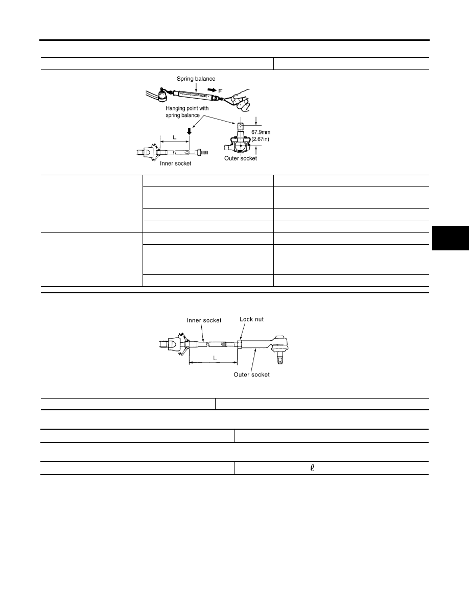
Outer socket
Swinging torque
0.3
−
2.9 N·m (0.03
−
0.29 kg-m, 3
−
25 in-lb)
Measurement on spring balance
●
Measuring point: cotter pin hole of stud
4.84
−
46.7 N (0.50
−
4.7 kg-f, 4
−
34 lb-f)
Rotating torque
0.3
−
2.9 N·m (0.03
−
0.29 kg-m, 3
−
25 in-lb)
Axial end play
0.5 mm (0.020 in) or less
Inner socket
Swinging torque
1.0
−
7.8 N·m (0.11
−
0.79 kg-m, 9
−
69 in-lb)
Measurement on spring balance
●
Measuring point: L mark see above,
L=83.2 mm (3.276 in).
12.1
−
93.7 N (1.3
−
9.5 kg-f, 9
−
69 lb-f)
Axial end play
0.2 mm (0.08 in) or less
Tie-rod maximum length “L”
84.0 mm (3.31 in)
SGIA0358E
SGIA0167E
Oil pump relief hydraulic pressure
8.0
−
8.8 mPa (81.60
−
89.76 kg/cm
2
, 1160.0
−
1276.0 psi)
Fluid capacity
Approx. 1.0
(2 1/8 US pt, 1 3/4 Imp pt)