Nissan Pathfinder (2007 year). Manual - part 235
FUEL INJECTOR AND FUEL TUBE
EM-37
C
D
E
F
G
H
I
J
K
L
M
A
EM
2007 Pathfinder
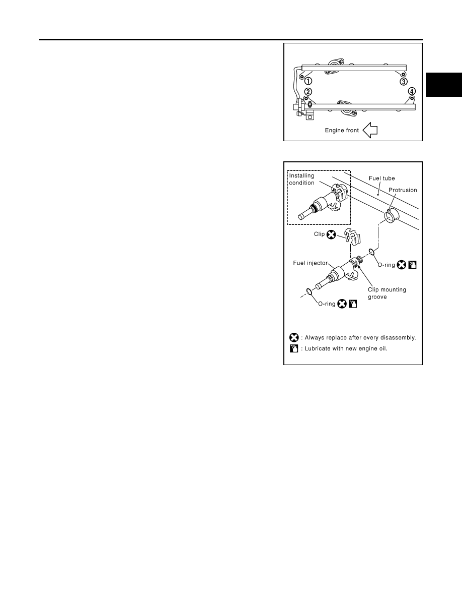
5.
Loosen bolts in reverse order as shown, and remove fuel tube
and fuel injector assembly.
CAUTION:
Do not tilt it, or remaining fuel in pipes may flow out from
pipes.
6.
Remove bolts which connects fuel tube (RH) and fuel tube (LH).
7.
Remove fuel injector from fuel tube as follows:
a.
Carefully open and remove clip.
b.
Remove fuel injector from fuel tube by pulling straight.
CAUTION:
●
Be careful with remaining fuel that may go out from fuel
tube.
●
Be careful not to damage injector nozzles during
removal.
●
Do not bump or drop fuel injector.
●
Do not disassemble fuel injector.
8.
Disconnect fuel tube (RH) from fuel tube (LH).
9.
Loosen bolts, to remove fuel damper cap and fuel damper, if necessary.
PBIC2902E
PBIC2999E