Nissan Pathfinder (2007 year). Manual - part 155
TROUBLE DIAGNOSIS
EC-107
C
D
E
F
G
H
I
J
K
L
M
A
EC
2007 Pathfinder
13
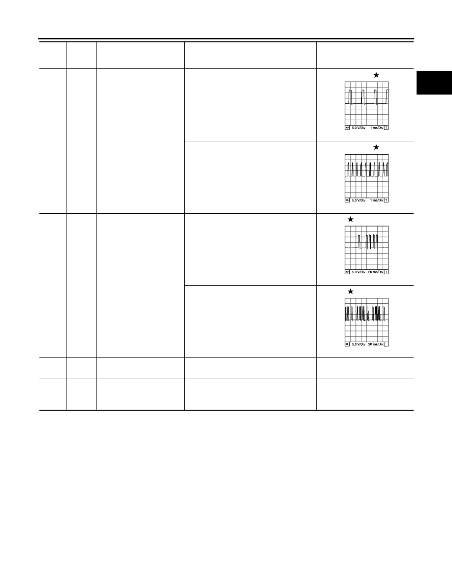
G
Crankshaft position sensor
(POS)
[Engine is running]
●
Warm-up condition
●
Idle speed
NOTE:
The pulse cycle changes depending on
rpm at idle
Approximately 10V
[Engine is running]
●
Engine speed: 2,000 rpm
Approximately 10V
14
Y
Camshaft position sensor
(PHASE) (Bank 2)
[Engine is running]
●
Warm-up condition
●
Idle speed
NOTE:
The pulse cycle changes depending on
rpm at idle
1.0 - 4.0V
[Engine is running]
●
Engine speed: 2,000 rpm
1.0 - 4.0V
15
W
Knock sensor
(Bank 1)
[Engine is running]
●
Idle speed
Approximately 2.5V
16
BR
A/F sensor 1 (Bank 2)
[Engine is running]
●
Warm-up condition
●
Engine speed: 2,000 rpm
Approximately 1.8V
Output voltage varies with air
fuel ratio.
TER-
MINAL
NO.
WIRE
COLOR
ITEM
CONDITION
DATA (DC Voltage)
PBIB1041E
PBIB1042E
PBIB1039E
PBIB1040E