Nissan Pathfinder (2007 year). Manual - part 63
DUCTS AND GRILLES
ATC-155
C
D
E
F
G
H
I
K
L
M
A
B
ATC
2007 Pathfinder
Grilles
Removal and Installation
EJS004Q5
DEFROSTER NOZZLE
Removal
1.
Remove the front heater and cooling unit assembly. Refer to
ATC-141, "FRONT HEATER AND COOLING
.
2.
Remove the defroster nozzle.
Installation
Installation is in the reverse order of removal.
RH AND LH SIDE DEMISTER DUCT
Removal
1.
Remove the front heater and cooling unit assembly. Refer to
ATC-141, "FRONT HEATER AND COOLING
.
2.
Remove the center console. Refer to
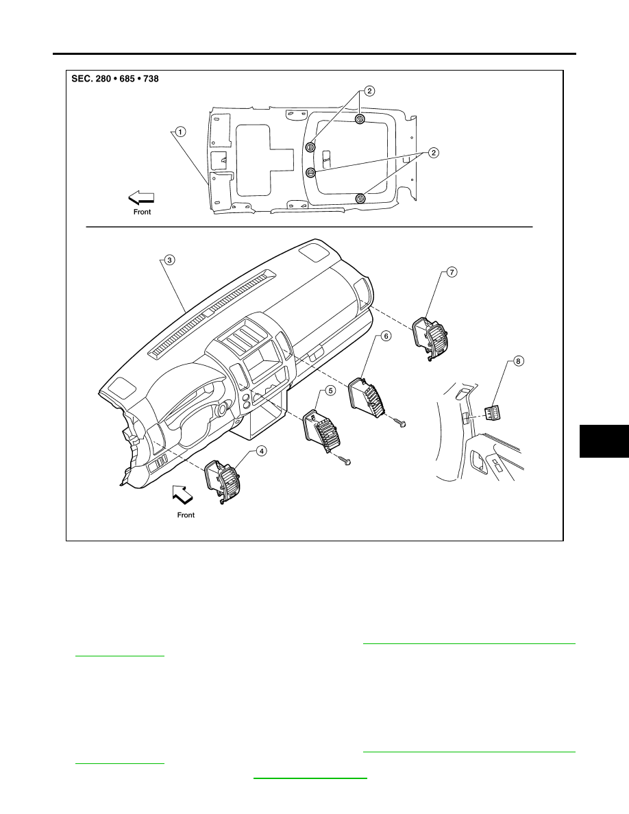
WJIA1404E
1.
Headliner
2.
Overhead grilles
3.
Instrument panel and pad assembly
4.
LH side ventilator grille
5.
LH ventilator grille
6.
RH ventilator grille
7.
RH side ventilator grille
8.
RH side demister grille