Nissan Pathfinder (2005 year). Manual - part 456
 

  Index      Manuals     Nissan Pathfinder (2005 year) - Service and Repair Manual


Search            copyright infringement  


Content      ..     454      455      456      457     ..


Nissan Pathfinder (2005 year). Manual - part 456


TRANSFER CONTROL UNIT

TF-267

[TX15B]

C

E

F

G

H

I

J

K

L

M

A

B

TF

2005 Pathfinder

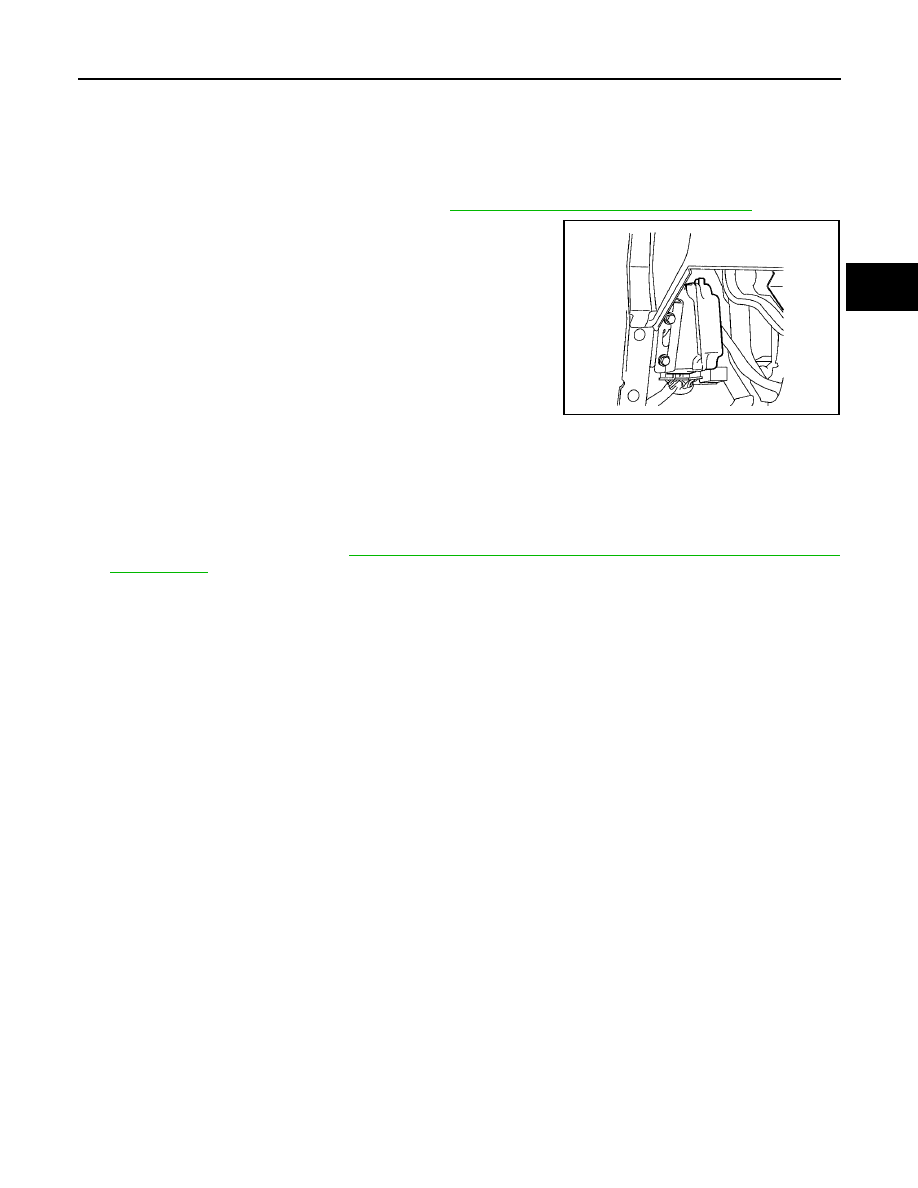
TRANSFER CONTROL UNIT

PFP:33084

Removal and Installation

EDS001LQ

REMOVAL

1.

Switch 4WD shift switch to 2WD and set transfer assembly to 2WD.

2.

Turn the ignition switch OFF and disconnect negative battery terminal.

3.

Remove the lower instrument panel LH. Refer to

IP-13, "LOWER INSTRUMENT PANEL LH"

.

4.

Disconnect the two transfer control unit connectors.

5.

Remove the transfer control unit bolts.

6.

Remove the transfer control unit.

INSTALLATION

Installation is in the reverse order of removal.

When installing the transfer control unit, tighten bolts to the specified torque.

After the installation, check 4WD shift indicator pattern. If NG, adjust position between transfer assembly
and transfer control unit. Refer to

TF-185, "Precautions for Transfer Assembly and Transfer Control Unit

Replacement"

.

LDIA0168E

Transfer control unit bolts

: 3.4 N·m (0.35 kg-m, 30 in-lb)

TF-268

[TX15B]

FRONT OIL SEAL

2005 Pathfinder

FRONT OIL SEAL

PFP:38189

Removal and Installation

EDS001LR

REMOVAL

1.

Partially drain the transfer fluid. Refer to

MA-25, "Changing Transfer Fluid"

.

2.

Remove the front propeller shaft. Refer to

PR-5, "Removal and Installation"

.

3.

Remove the companion flange self-lock nut, using Tool.

4.

Put a matching mark on top of the front drive shaft in line with
the mark on the companion flange.

CAUTION:

Use paint to make the matching mark on the front drive
shaft. Do not damage the front drive shaft.

5.

Remove the companion flange, using suitable tool.

6.

Remove the front oil seal from the front case, using Tool.

CAUTION:

Do not damage front case.

Tool number

: KV40104000 (

)

LDIA0142E

SDIA2779E

WDIA0193E

Tool number

: ST33290001 (J-34286)

LDIA0144E

FRONT OIL SEAL

TF-269

[TX15B]

C

E

F

G

H

I

J

K

L

M

A

B

TF

2005 Pathfinder

INSTALLATION

1.

Install the front oil seal until it is flush with the end face of the
front case, using Tool.

CAUTION:

Do not reuse oil seal.

Apply petroleum jelly to oil seal.

2.

Align the matching mark of the front drive shaft with the match-
ing mark of the companion flange, then install the companion
flange.

3.

Install the self-lock nut and tighten to the specified torque, using
Tool. Refer to

TF-276, "COMPONENTS"

.

CAUTION:

Do not reuse self-lock nut.

4.

Install the front propeller shaft. Refer to

PR-5, "Removal and

Installation"

.

5.

Refill the transfer with fluid and check fluid level. Refer to

TF-

193, "FILLING"

.

6.

Check the transfer for fluid leakage. Refer to

TF-193, "FLUID

LEAKAGE AND FLUID LEVEL"

.

Tool number

: KV38100500 (

)

LDIA0145E

SDIA2214E

Tool number

: KV40104000 (

)

LDIA0147E

TF-270

[TX15B]

REAR OIL SEAL

2005 Pathfinder

REAR OIL SEAL

PFP:33140

Removal and Installation

EDS001LS

REMOVAL

1.

Partially drain the transfer fluid. Refer to

MA-25, "Changing Transfer Fluid"

.

2.

Remove the rear propeller shaft. Refer to

PR-10, "Removal and Installation"

.

3.

Remove the dust cover from the rear case.

CAUTION:

Do not damage the rear case.

4.

Remove the rear oil seal from the rear case, using Tool.

CAUTION:

Do not damage the rear case.

INSTALLATION

1.

Install the rear oil seal until it is flush with the end face of the rear
case, using Tool.

CAUTION:

Do not reuse oil seal.

Apply petroleum jelly to oil seal.

2.

Apply petroleum jelly to the circumference of the new dust cover.
Position the dust cover using the identification mark as shown.

CAUTION:

Do not reuse dust cover.

Position the identification mark at the position shown.

WDIA0127E

Tool number

: ST33290001 (J-34286)

LDIA0139E

Tool number

: KV38100500 (

)

LDIA0140E

SDIA2208E

REAR OIL SEAL

TF-271

[TX15B]

C

E

F

G

H

I

J

K

L

M

A

B

TF

2005 Pathfinder

3.

Install the dust cover to the rear case, using Tool.

CAUTION:

Do not reuse dust cover.

Apply petroleum jelly to dust cover.

4.

Install the rear propeller shaft. Refer to

PR-11, "INSTALLATION"

.

5.

Refill the transfer with fluid and check fluid level. Refer to

TF-

193, "FILLING"

.

6.

Check the transfer for fluid leakage. Refer to

TF-193, "FLUID

LEAKAGE AND FLUID LEVEL"

.

Tool number

: KV40105310 (

)

PDIA0116E

TF-272

[TX15B]

TRANSFER CONTROL DEVICE

2005 Pathfinder

TRANSFER CONTROL DEVICE

PFP:33251

Removal and Installation

EDS001LT

REMOVAL

1.

Switch the 4WD shift switch to 2WD and set the transfer assembly to 2WD.

2.

Disconnect the transfer control device connector.

3.

Remove the breather hose from the transfer control device.

4.

Remove the bolts and detach the transfer control device.

INSTALLATION

1.

Install the O-ring to the transfer control device.

CAUTION:

Do not reuse O-ring.

Apply petroleum jelly to O-ring.

2.

Install the transfer control device.

a.

Turn the control shift rod fully counterclockwise using a flat-
bladed screwdriver, and then put a mark on the control shift rod.

b.

Align the transfer control device shaft cutout with the mark on
the control shift rod, and install.
NOTE:
Turn the transfer control device when the transfer control device
connection does not match.

LDIA0136E

LDIA0137E

PDIA0119E

PDIA0120E

TRANSFER CONTROL DEVICE

TF-273

[TX15B]

C

E

F

G

H

I

J

K

L

M

A

B

TF

2005 Pathfinder

c.

Tighten the bolts to the specified torque. Refer to

TF-276,

"COMPONENTS"

.

3.

Install the breather hose to the transfer control device.

4.

Connect the transfer control device connector.

5.

After the installation, check the 4WD shift indicator pattern. If
NG, adjust the position between the transfer assembly and
transfer control unit. Refer to

TF-185, "Precautions for Transfer

Assembly and Transfer Control Unit Replacement"

.

SDIA2212E

TF-274

[TX15B]

AIR BREATHER HOSE

2005 Pathfinder

AIR BREATHER HOSE

PFP:31098

Removal and Installation

EDS001LU

Refer to the figure for air breather hose removal and installation information.

CAUTION:

Make sure there are no pinched or restricted areas on the air breather hose caused by bending or
winding when installing it.

Install the air breather hose into the breather tube (metal connector) and transfer control device
(case connector) until the hose end reaches the base of the tube.

SDIA2409E


Content      ..     454      455      456      457     ..